Monthly Archives: January 2009

To Oscillate, or not to Oscillate…

Or more precisely, is it oscillating, or is it not oscillating?

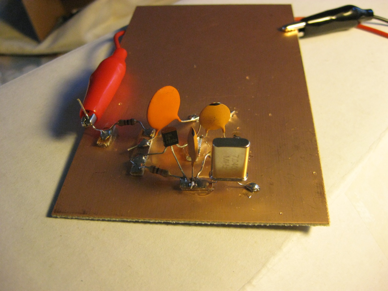
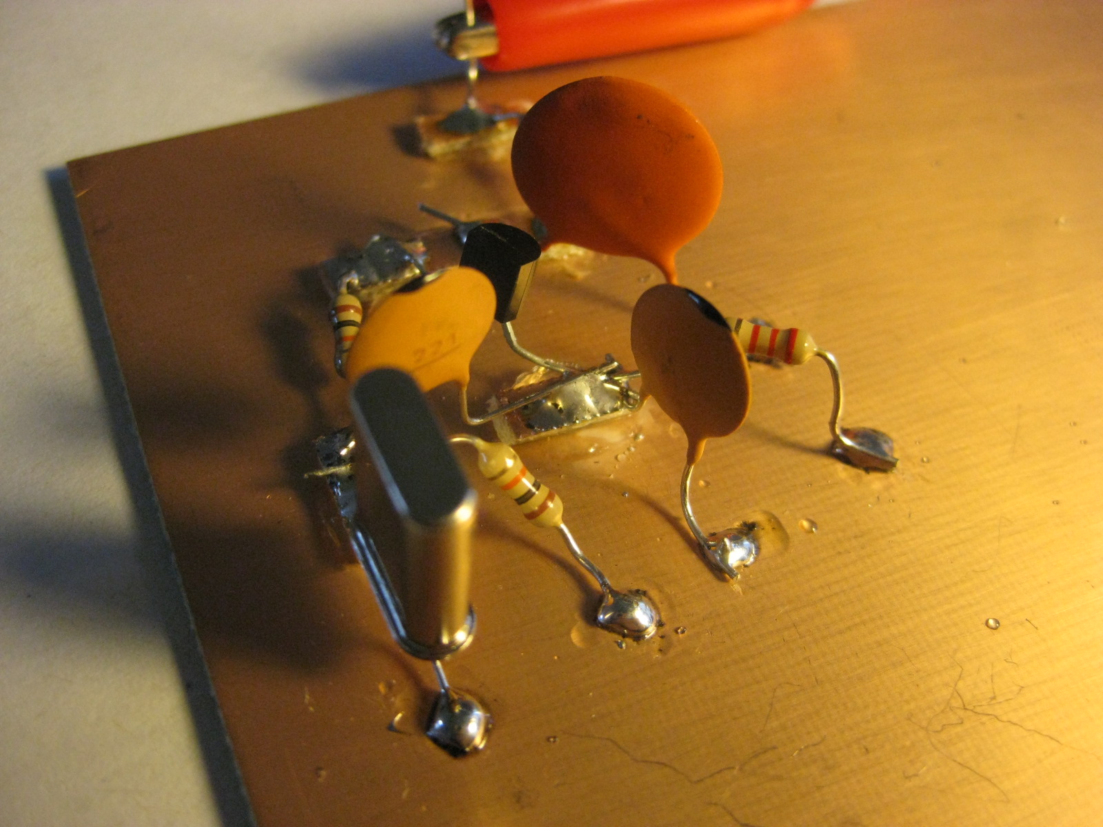
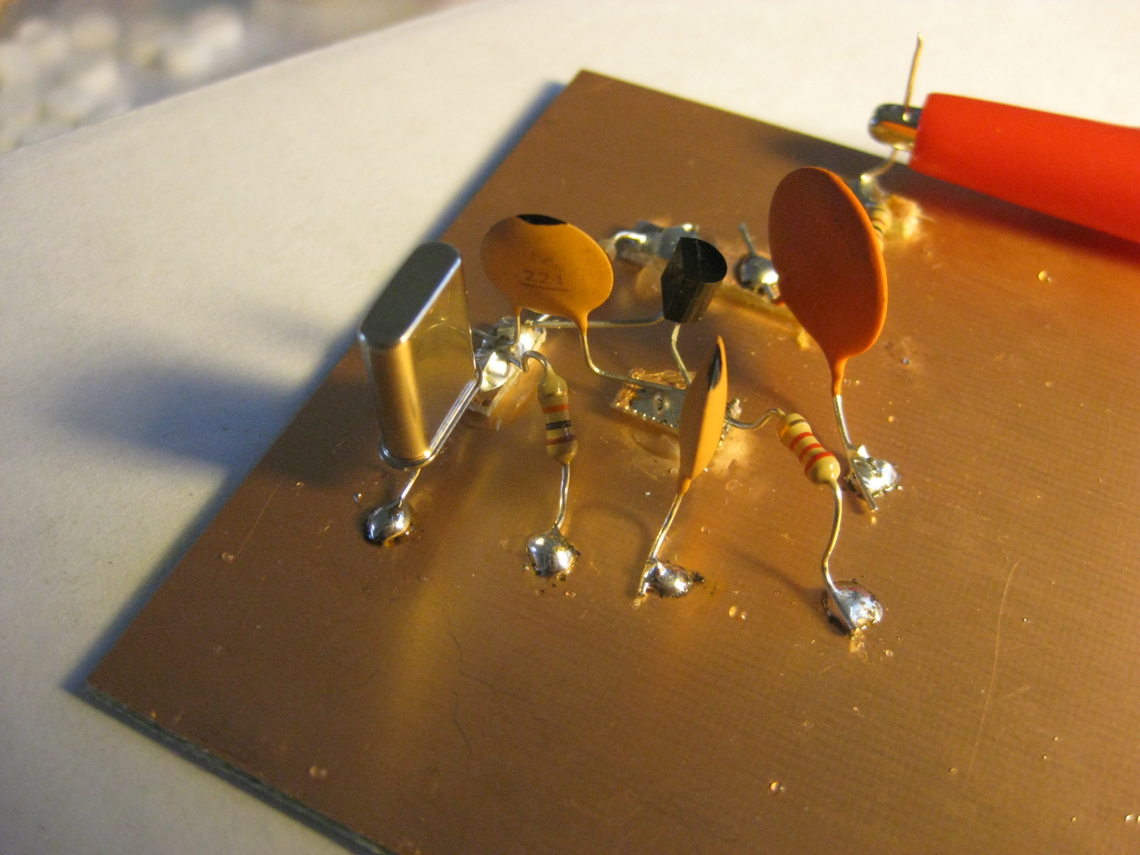
This is my first attempt at actually trying to build a circuit using Manhattan style construction (so please, be kind!) I fetched the oscillator circuit from EMRFD, and tacked it together with some parts from my junkbox. The only substitution that I made was that the two 390pf capacitors were replaced with 220pf capacitors. My understanding (limited as it might be) is that this is parallel capacitance for the crystal, and should move the oscillating frequency somewhat closer to the frequency of the crystal (in this case, 7.040 Mhz) than the specified design.

Here are some photos:

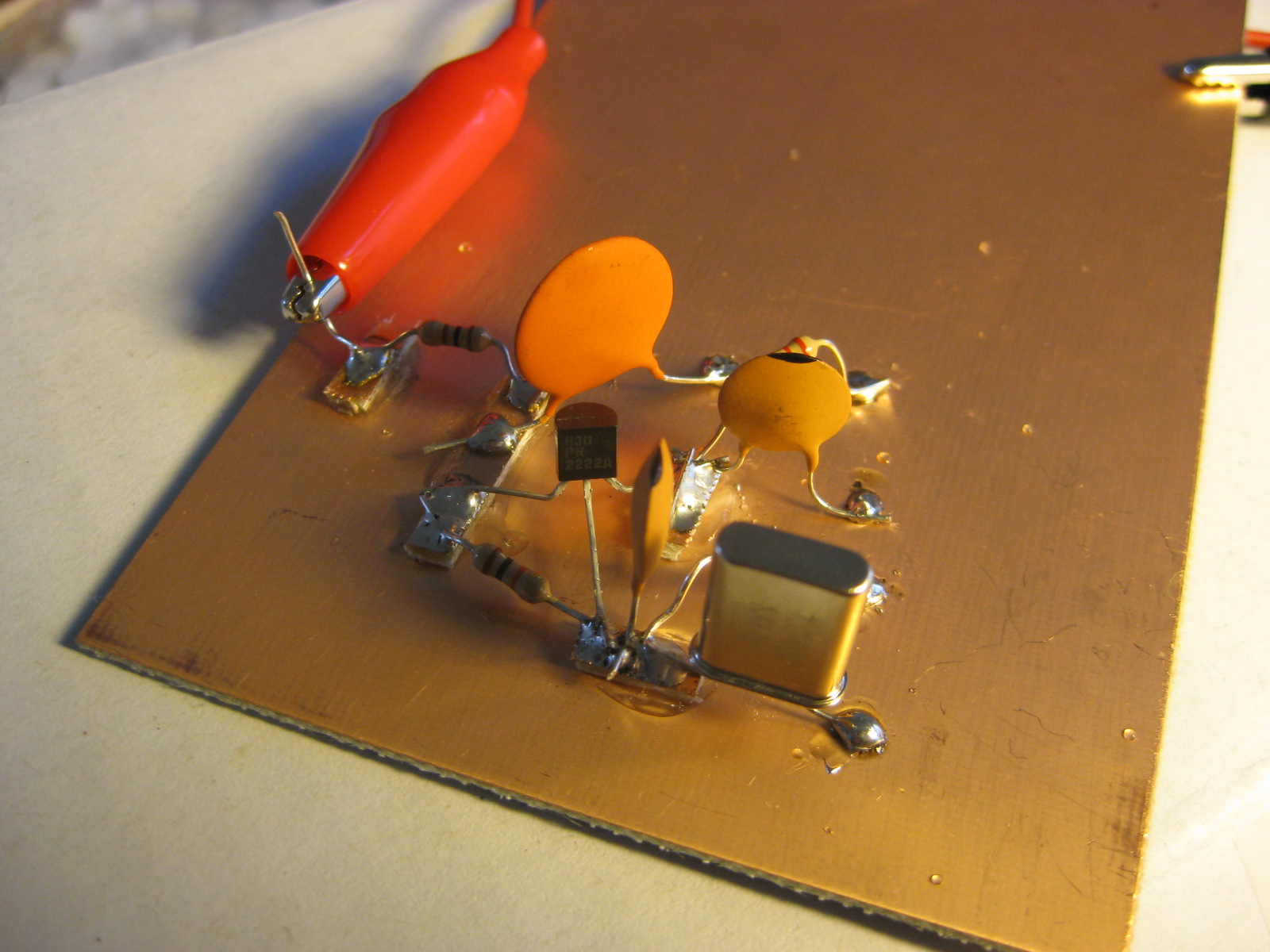
EMRFD says that this should oscillate at very low voltage levels, so I powered it up with a 9 volt battery. No magic smoke was released, but fishing around the design frequency using my FT-817ND, I heard nary a trace of it anywhere near the design frequency. If I had an oscilloscope, it would probably be pretty easy to tell, but I don’t (hey, I told you I was new at this). I fished around with my multimeter a bit, measuring continuity and the like. The overall resistance between the positive voltage supply and ground is about 19k ohms, indicating an overall current draw of about 0.4ma (with the 9 volt supply). That seems low, but maybe not excessively low. Measuring the base voltage on the transistor, I get about 3.35 volts. Again, that seems reasonable to me.

For all I know, it could be oscillating, but at a low power level. I’d rather not proceed building the buffer amplifier until I was reasonably sure the oscillator was working. Any ideas, oh wisdom of the internet?

Addendum: On a whim, I swapped out a color burst crystal (3.579Mhz) and it started to oscillate. As i tough various components, I get a stronger signal, but relatively little frequency shift.

I’m hypothesizing that my substitution of the 220pf for the 390pf ones wasn’t entirely kosher.

Addendum: Here’s some video:


Addendum2: Heh. I think the transistor was in backwards. Reversing it, and it now oscillates on 40m. Thanks to Eldon Brown for the suggestion, which made me double check. Next stop: a buffer amplifier!

Addendum3: It oscillates at 7.038616 Mhz or so.

free university lectures on lecturefox

I must admit: I’m separated by 20 years from my college experience, and I still miss it. Not the parties, being single, or even being young, but simply the challenge and excitement of being in an evironment where you are encouraged to learn about interesting topics. I love academia. I like being in the classroom. I like lectures. Heck, I even like doing homework and testing my understanding with tests.

Well, I may not be able to go back to college, but at least the Internet provides a wide variety of material available, much of it from schools much better than the one I atteded. Check out lecturefox.com’s collection of free university lectures. They have lectures on physics, chemistry, computer science and mathematics. Awesome.

My Big Fat Ham Radio Epiphany at KE9V.net

Over at KE9V.net, Jeff has had an epiphany. I thought I’d give a couple of comments.

Many hams seem to be completely paralyzed that the hobby that they love is dying, or at least changing into something they no longer think is truly amateur radio. I see this on amateur radio forums more than I do on the air. I suspect that is because those who actually operate are too busy having fun making contacts to waste much energy worrying about the future of ham radio. Ironically, I think that they are doing more to actually advance ham radio than those who primarilly sit on the sidelines and lament its passing.

Nostalgia does have a reasonable place in any balanced view of the entirety of ham radio. That’s rather the key point: we must balance our feelings of nostalgia with our desire to continue to self-train, to spread good will internationally, and to serve our local communities in times of need. We must realize that nostalgia is not a very good recruiting tool. Listing to someone in their sixties (or older) talk about ham radio operation back in the sixties does little to motivate a young person to begin operating today, as interesting as the story might be. The reason is simple: that young person cannot go back in time and gain the same feelings of accomplishment that our Elmer’s did. The world has changed, and there is no going back.

I like hearing stories about the old days of radio. I like researching what the early pioneers did. I like the stories of ordinary hams contacting cosmonauts on the Mir, or the first EME communications. There is no reason not to continue to enjoy these things which help us educate us about ham radio’s proud past.

What we should recognize is that talking about ham radio is not the same thing as doing ham radio. If we want to entice others to actually do ham radio, we can’t do so by just talking about it, we have to actually do it ourselves.

Mystery of Sodium Acetate

You can find some occasionally surprising stuff on youtube. I’d seen a number of videos illustrating rapid crystallization of supersaturated mixtures of sodium acetate, but this is something a little different that I hadn’t seen before. Does anyone know what’s really going on here?


httpv://www.youtube.com/watch?v=eNvZLTkj2kw

P.S. It’s “iodized” salt, not “ionized”.

More Good Ham Video Goodness: Jeremy Chase, N1JER

I ran across Jeremy Chase’s nifty ham radio website when it was mentioned on QRP-L. It’s really quite cool: Jeremy is just beginning to get on the air using kit transceiver (a Wilderness SST), a kit tuner (One of Steve Weber’s cool kits), and a homebrew dummy load that he put together, along with about the most homebrew Morse Key I can remember seeing! Check out his website, and especially this video.


N1JER makes contact with K8MAD from Jeremy Chase on Vimeo.

More Meter Madness

Okay, after having read WB8ICN’s postings on QRPedia, I decided to try to measure the impedence of both of my meters. I dug a 1.5M ohm resistor out of the pile, and hooked some jumper leads to it. I then did the following:

  1. Measure the resistance of the resistor, using the DVM as an ohm meter (R)
  2. Measure the voltage of a 9 volt battery, using the DVM as a volt meter. (V)
  3. Hook the resistor in series with the battery, and measure the resulting voltage. (Vm)

What we are looking for is the resistance of the meter, which we will call Rm. A little math should show that Rm = R * Vm / (V – Vm). Okay, that heavy lifting aside, let’s see what we discovered about my two meters:

For my better meter, a nice Radio Shack PC interfaceable multimeter, I got the following readings:

  1. R = 1.496M ohms
  2. V = 9.24 volts
  3. Vm = 7.94 volts

Plugging these values into the formula, we get a value for Rm of 9.18M ohms, considerably off from the 10M ohms that we used as the “nominal” value. Later, I’ll go back and work up the correction factor for the previous nights example, but for now, let’s move onto my second meter, a cheapy $20 one that I’ve used mostly to check my car battery and continuity. I recorded the following values:

  1. R = 1.480M ohms
  2. V = 9.14 volts
  3. Vm = 3.68 volts

Plugging these values in, I get about .997M ohms, or about 1Mohm! No wonder my previous readings were so crazy, with the 4.4M ohm resistance of my series resistors, this thing was dividing the peak value down considerably.

Okay, let’s go back to my dummy load experiment. First, on meter number one, we find that Rm of 9.18M ohms. If we go through my various calculations and correct for the measured values, we find that the output power should be around 4.71 watts. Doing the same for measurement number two, we’d get an output power of around 4.67 watts, both in excellent agreement!

(Note, I didn’t measure the voltage drop of the diode, I’m assuming 0.7 v. The data sheet says the maximum drop would be 1v).

The Tale of Two Meters

Well, I’ve been mucking around with my RF probe circuitry a bit tonight, and encountered something pretty strange. I have two digital multimeters lying around, and my newly rebuilt RF probe/dummy load that I described earlier. I hook one multimeter to it, and I get a reading of 14 volts. I get my other cheapie meter, and I get a reading of about four volts. Yet, both are probably “correct”. How can that be?

Well, first, let’s review the circuit that I have revised to:

diodes1

I have used a different diode (a 1N914, which is probably better than the 1N4001 that I had in there previously, but not as good as the germanium diode you see in the schematic) and didn’t have any 4.7M ohm resistors, so I hooked two 2.2M ohm resistors in series. The voltage drop for the 1N914 is probably about 0.7 volts, but haven’t measured it. The purpose of the 4.7M ohm resistor is to convert the peak voltage (as gathered in the capacitor) to RMS voltage. How does this work? Well, if you imagine that the meter has some input resistance, then we basically have a voltage divider: the voltage that is measured by the voltmeter is the peak voltage, multiplied by the resistance of the meter divided by the sum of the meter resistance and the 4.7M ohm resistor. In years past, where this design was first put out, the common impedance for meters was around 11M ohms. So, the voltage we get out is the peak voltage * 11 / (11+4.7) = .7006 * the peak voltage. The peak voltage is sqrt(2) times the RMS voltage, so the RMS is the peak divided by sqrt(2). 1.0 / sqrt(2), which is .7071 or so, so the 4.7 Mohm resistor would be about right for a voltmeter with 11M ohm resistance.

Reading up on the subject, modern digital volt meters have an input impedence of 10Mohms. To figure out what size of a resistor we need for that, we solve 10 / (10 + R) = 1/sqrt(2) for R, and we end up with about 4.1M ohm resistance. I ended up approximating this by two 2.2M ohm resistors, which is closer, but still not perfect.

Okay, so that’s my thinking. So, I jumper the thing to one of two meters, and get a reading of about 14 volts. This indicates an output power of 14*14/50 or 3.92 watts (this was my FT-817 in 5 watt mode). The number is small, but I expected that. I haven’t accounted for two things: either the voltage drop of the diode, nor the problem with using the wrong series resistors. Instead of dividing the peak by the sqrt(2), I am multipling by about .694. Still assuming a 10M ohm resistance, my 14 volts should have been about 14.17 volts, plus the voltage drop (say .7 volts). This works out to about 4.42 watts. In the right ballpark, given that we didn’t really measure the impedence of the meter.

But here’s the odd thing! I hooked it to another, cheap meter of mine, and got only 3.92 volts! This is a budget DVM, which probably cost me about $10 that I have used mostly to check to see if my car battery is dead, but the difference is startling. The only conclusion I can draw is that the cheaper meter has a dramatically different impedence, probably around 0.5 Mohms. To test this idea, I measured the peak voltage at the junction between the cap and the diode, and both meters were in agreement. Interesting!

Through a coincidence, WB8ICN has been examining the same issue on QRPedia. He suggests using a potentiometer hooked to a regulated power supply, and measuring the voltage as you adjust the potentiometer until it reaches half the supply voltage, then the potentiometer is set to the impedence of your meter. Of course, with a little algebra, you don’t need to do that: you can just measure the voltage drop of any resistor with a resistance of a 1M ohm or so, and work it out. I’ll probably do that for both my meters, and then stick a little note on them so I remember.

Oh well, that’s my electronics tinkering for the day.

Aircraft reflection? Or something else?

This duplicates a posting I made on the wsprnet.org website.

Aircraft reflection? Or something else? | WSPRnet
On Saturday, Jan 10th, I had my transmit-only beacon that I wrote sending both a visual MEPT indicator (the MV that you can see in the attached image) and the WSPR beacon, and tried out a simple program that simultaneously records, and later makes an FFT display of that portion of the band.

It seems to work!

I’m curious though about the brighter of the wspr messages visible here, which seems to have a shadow which arcs down to meet it. Is this the result of an aircraft reflection? There are some fairly close stations here (such as NN6RF) which conceivably could be reflecting off aircraft landing at Oakland airport, but I’m surprised that the signal level could be so high on the 30m band. I believe that such reflections can only occur if the source is reasonably close to the aircraft, correct?

aircraft

I see a couple of other, similar traces in the 2 hour recording I did, which you can peruse here.