Daily Archives: 12/7/2009

Tank Circuits…

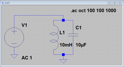
Okay, time to work my way through some more complicated (but stll simple) examples. First of all, let’s consider a simple parallel LC circuit. Here is one with a 10uF capacitor and a 10mH inductor in parallel with an AC source:

2009-12-07_2156

We can compute the resonant frequency using the classic formula:

          1
f = ------------
        __   ___
    2.0 || \/L C

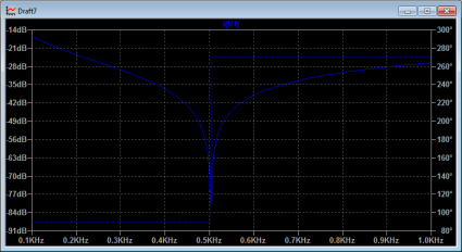
Plugging in our values for L and C, we end up with a resonant frequency at approximately 500 Hz (more precisely, about 503 Hz). So, let’s use LTSpice to analyze the circuit using AC analysis, sweeping the frequency from 100Hz to 1000Khz. If we look at a graph of the current draw through the voltage source from this parallel LC circuit, we see the following:

2009-12-07_2157

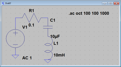
The parallel LC circuit’s current draw drops to zero at the resonant frequency. It’s impedance goes to infinity at the resonant frequency, the tank doesn’t draw any current. Let’s compare it to the same circuit, but with the elements placed in series instead of in parallel. We’ll add a very tiny resistance as well.

2009-12-07_2224

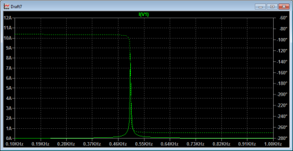
This circuit also resonates at the same frequency, but with radically different behavior. Let’s graph the current in this circuit:
2009-12-07_2257

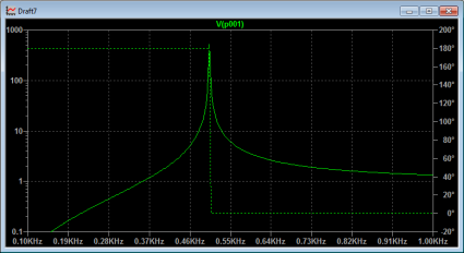
The currents through the circuit are huge, and peak at the resonant frequency. There are similarly huge voltages that appear across the capacitor.

2009-12-07_2202

All this is pretty basic stuff. I apologize for boring people with this, but I’m learning lots about using LTSpice by doing these basic exercises. It’ll eventually pay off by having a deeper understanding about how these circuits work.

Addendum: I was inspired by this chapter on resonance from Tony Kuphaldt’s second book on AC electric circuits. These books are part of the Open Book Project, and are available for free download. I’m gonna make good use of these.
Power Transfer Math

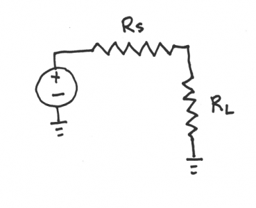
As I might have mentioned, I am trying to teach myself a bit about electronics and radio design. I find the problem with being self taught is that often you read something, and it doesn’t seem clear to you why it should be so, and you uncover the basic lack of understanding that you have to go back and fill in before the later material makes sense. This happened to me while I was trying to work through some more amplifier designs, and I realized that I had a basic misconception about how impedance matching actually worked, and this was perhaps even more basic, and could be illustrated with a simple circuit, consisting of a voltage source, and then in series a source resistance RS and a load resistance RL. The question is given an RS, what value of RL maximizes the power dissapated in the load RL?

power

Well, it’s not really too hard to figure out. First, we can determine the total current going around the loop. For a voltage V, the current is simply:

       V
I = -------
    R  + R
     S    L

From this we can easily determine the voltage drop across RL:

      R  V
       L
V  = -------
 L   R  + R
      S    L

And, since we know the current through and the voltage across the resistor, we can determine the power as their product:

            2
        R  V
         L
P  = ----------
 L            2
     /R  + R \
     \ S    L/

When is power maximized? Well, we can differentiate the power equation with respect to RL, and we get:

                           2
dP         2         2 R  V
  L       V             L
--- = ---------- - ----------
dR             2            3
  L   /R  + R \    /R  + R \
      \ S    L/    \ S    L/

Setting this equal to zero, and solving for RL, we find that a maximum occurs where RL equals RS, in other words, power is maximized when the source and load resistances are matched. The total disappated by RL is then:

      2
     V
P  = ---
 L   4 R

Thus, if we had a load of 50 ohms and a voltage source of 12 volts, we’d end up with a maximum power of 720 mw.

Addendum: As a double check, the power passing through both resistors is V^2 / 2R, which would have been 1.44 watts, and obviously since both resistors are the same, the power is evenly split between the two.

Addendum2: I forgot to mention what I was confused about. It’s not really this (which occurs in DC circuits) but the corresponding circuit which occur in AC circuits with complex impedances. I’ll work through this later.

Addendum3: Hmm. Subscripts and superscripts seem to not work right with this theme. I’ll fix it.