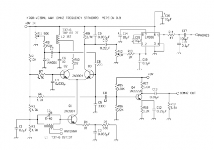
While scanning QRP-L today, I found an interesting link to a project which gave some details about a little WWV receiver that can serve as a frequency standard. I haven’t had the time to work out how it all works, but it looks reasonably straightforward:
Here’s the original schematic from Chuck Adams, K7QO:
Nick, WA5BDU has some variations and additional comments which are interesting:

Mark,
I built this receiver a while ago:
http://www.vk2zay.net/article/154
Works very well. I like the improvements, in particular the tuned front-end and LO-out buffering. Mine doesn’t have an in-built AF amplifier I just use the bench amplified speaker whenever I want to use it.
Regards,
Alan
If you build this receiver (as I have), and get it to work, you’re a better technician than I. I have spent the entire day finding parts, and taking extra special care in following the diagram. However, there are several errors, and I would like to point them out. First, there is no mention of what size wire to use for the transformers. Second, there is no such animal as a ” 1N400X ” diode. I took a chance that it was meant to be a 1N4007. C5 is labelled as a ” 3300 ” (I assume pf) capacitor, but then again, it could have a polarity (+). I had planned on giving this to one of my Grandchild (who is showing some interest in Electronics) for Christmas. Needless to say, it didn’t happen. I have ran the circle several times, and I’ve seen it numerous times, an individual create’s a circuit, builds it, and it may or may not work, but they are fast to throw their design on the Web, without first proof reading it. Then you get some sumuck like me, spends an entire day finding parts and try to create the same circuit. The result I got, is a lot of rushing noise, no WWV, the R11 does exactly nothing, the volume control does work, and the 10Mhz Out just varies all over the place. Injecting a sig gen in the front end, shows the strongest signal at 7.555Khz. I take some of the blame, for not knowing the wire size, I took a guess and used # 28. I would like for the receiver to work as it should, so is there any hope ?? In need of help. Jim WA5WRE
I found this autodyne circuit a couple of weeks ago. I’ve been looking for a reasonably-accurate frequency reference to calibrate my frequency counter. I had a PCB made, and put it together. My circuit uses a CA3146E transistor array which I found on eBay. I am using the original design by K7QO & VE3DNL, which can be found on the Brainwagon site.
I used a different L1 at first, and the oscillator would not run. Reducing the value of R1/10K fixed that, but I ended up adding a regulated 12V supply instead. I’m now using FT37-43, 2T:2T, 150pF in parallel with C2.
I can hear some beats at certain settings, but no modulation at all. This is with a half-wavelength dipole through a commercial 300-75 ohm balun. Amplified LO output is 150mV-PP, not enough to trigger my 1989 ARRL Handbook frequency counter. So thus far it has been a total waste of time. If anyone else has suggestions for improvements, I’d love to hear ’em.
To Jim: I used 28ga wire on L1/L2 and a 1N4004 diode. C6 is a trim-cap, but as the circuit is very sensitive, it should be something more stable. I paralleled it with 20pF because the range (in my case) was too high. If you are not getting the right range, try a slightly higher B+ or lower the value of R1. Check L2 with LC meter: turns should be spread out. My first attempt resulted in over 1uH; it should be about 0.68uH.
I continued tweaking the circuit, using an air-variable cap for C6, and using one of the Radio Shack 9V pocket amplifiers (based on the LM386) at the output of the on-board LM386 to really boost the audio. One possible improvement would be to use the leftover transistor in the CA3146E (or equiv.) as a preamp, so the unit doesn’t require an external amplifier.
I am getting much better results. The LO output *does* track the received station, as described by Nick (see link in article). I can usually hear WWV or WWVH, sometimes both at the same time. I was able to use the LO output to also tweak my home-built ARRL frequency counter (needed more localized supply filtering) and so now I have achieved the goals I set out to accomplish with this unit. I more than doubled the sensitivity of the frequency counter 10 MHz front-end, improved the stability of the 550 MHz front-end, and got it calibrated within a Hertz or two.