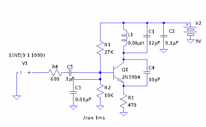
Schematic for the Micro FM transmitter
Tetsuo Kogawa’s circuit is pretty well documented, but not in conventional schematic form. I decided to enter it into LTSpice to see what it could make of it, and decided to go ahead and put the schematic online here, with perhaps a few comments:
I’ve set this up more or less as I built the circuit: in my circuit C1 is a small air variable cap that goes up to about 18pF, so I’ve set it to 12pF here. I use a 9V supply, so that’s what I put in for V2. I changed the power supply bypass cap to be 0.1uF instead of 0.01uF, since I have a bag of 0.1uF ones, and it doesn’t seem to affect the circuit. The L1 value of 0.08uH was determined by plugging numbers into the formula for an air wound solenoid coil: it’s probably only very roughly what the inductance actually is. Instead of the 2SC2001, I went ahead and put in the 2n3904 that I used. V1 is supposed to model the audio input, supplying a 1000 Hz, 1V amplitide sine wave to the modulation input. The output should be tapped from the emitter of Q1.
I’m going to experiment with the circuit a bit more: I’m particularly interested in jigging this up so I can figure out what the deviation is likely to be, and how it can be controlled, and how the biassing might change with a 6V supply.

I recall burning three or four weeks of a sabbatical getting Saccade.com on the air with Wordpress. So much tweaking…