One year ago today, I first published a link to The Broadcaster Project, a site which had several tips on using command line tools such as ffmpeg to assemble videos. I use a similar technique to do my more recent videos: I take the raw footage from the camera and resize it, denoise it, and add some overlaid text before uploading it to YouTube. Revisiting The Broadcaster Project, I see they have a few more recipes that can be useful, such as ones for assembling time lapse movies and the like. I also found a reference to youtube-upload, a command line python script that can automatically upload videos from the command line, a part of my process that I still did with the web interface.
Monthly Archives: May 2011
All LEDs are not created equal…
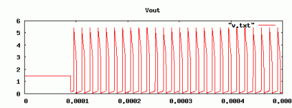
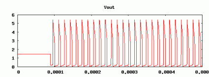
Of course I knew that all LEDs aren’t the same: they differ in color, size and brightness. They also differ in the forward voltage, reverse voltage and capacitance. When I simulated the Joule Thief with LTSpice, I just picked a random LED out of LTSpice’s catalog. When I simulated it, I got a waveform like this:
The voltage peaked over 5 volts, and the frequency was around 64khz.
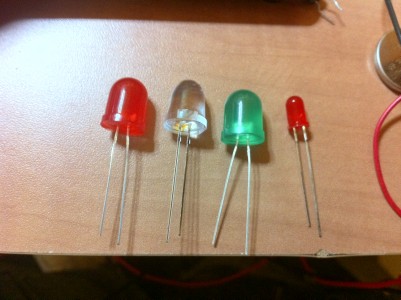
But what does the waveform really look like? I grabbed four LEDs out of my junkbox for testing, found a battery holder so I wouldn’t have to use three hands to get it hooked to my oscilloscope, and shot some pictures. First, the LEDS:
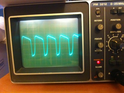
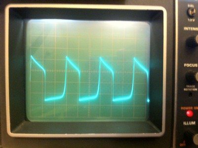
From left to right, they are a generic large red LED which used to be part of a throwie, a high-intensity lensed red LED from Radio Shack, a large green LED from radio shack, and a smaller common red LED from my junk box. I hooked them each up to the joule thief in turn. They all lit up. Here’s the generic red large LED:
The cycle time is a bit faster than I predicted: I estimate it’s oscillating at around 200khz. It’s voltage peaks are also quite a bit smoother and lower than the model I set up in LTSpice. For this picture, the vertical markings are just 0.5 volts, indicating a peak to valley of about 2 volts.
Here’s the larger, high intensity LED:
It’s much closer to a sine wave, and with a much higher peak to valley.
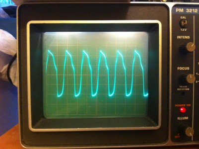
Here’s the green LED:
Much more trapezoidal, but with a catch: the voltage variations were so great I had to change the oscilloscope settings to 1 volt per vertical division.
And finally, here’s a smaller, run of the mill red LED…
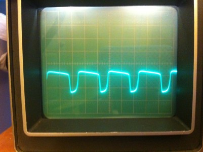
I left it at 0.5 volts per division, so you can see this is much lower.
So, what have I learned from all this? Well, not much at the moment. The green LED seems to match the waveform that I got from simulation most closely, but it’s oscillating at a higher frequency than predicted, and still has a somewhat lower peak to valley voltage range. I’ll probably go back and tinker with the LTSpice model some more (probably by modifying the characteristics of the diode, as well as varying the inductance of the transformer) and see if I can capture the variety of waveforms that I see here.
It was a fun excuse to hook up the scope.
Update re: the HamCan.
Dave, NM0S and designer of the HamCan, a kit that I previously assembled, but had some difficulty with nicely contacted me via email today so ask if he could be of help. I’m pretty sure that whatever the issue is, it’s my own fault, but hopefully with some patient help from Dave I can figure it out over the next week or so if I can find some time to be in the workshop. It was darned nice of him to drop me an email with an offer of help.
My trip down memory lane leads me back to TOPS-10 and the PDP-10
I’m going to be nostalgic for a few moments. If you are too young to have any sense of nostalgia, skip ahead to the bold text below. You were warned!
A few days ago, I mentioned that I was having a bit of flashback, thinking of my first experience with time sharing computers back in the early 1980s. I was a child of the microcomputer revolution: I remember reading the articles on the Altaire and the COSMAC ELF in Popular Electronics (I was a precocious 12 year old at the time) and would eventually buy my first computer (an Atari 400) in 1980. By 1982, I was attending the University of Oregon and got my first exposure to “big” timesharing computers: their DEC 1091 (running TOPS10) and their IBM 4341.
I must admit, I wasn’t all that impressed at the time. I did take FORTRAN and COBOL classes though. I actually did JCL and punch cards on the IBM. I worked in the documents room at the Computing Center for a while, and I recall that I made some small modification to their software (in FORTRAN on the DEC) that kept track of check ins and check outs. It may have been the first time I was ever paid to program.
My recollection is that by late in my second year, I was obsessed with the idea of getting an account on one of the three VAX 11/750s in the computer science department, all of which ran BSD. To do that, I needed to start taking graduate level classes. So, I applied for them. I recall sitting in Professor Ginnie Lo’s compiler class on the first day. She asked me if I was a graduate student, and I replied “no”. She then asked me if she had given me permission to take her course. I replied (somewhat nervously, as I recall) “no”. To her credit, she allowed me to stay.
I digress.
Anyway, after getting accounts on one of the department’s Unix machines (and having access to another via my job in the Chemistry department) I found little reason to continue using the DEC 1091. I doubt that I used it more than a couple of times after 1985.
Which, in retrospect, is kind of too bad. The 36-bit DEC architectures were a significant part of computing history. The PDP-10 had a pretty nice architecture, with an interesting, symmetric instruction set. I didn’t have any appreciation of it back then, but with the wisdom granted by experience (and no doubt a certain amount of nostalgia) I find that it is actually pretty interesting.
So… I embarked on a mini-project to recreate the environment that I dimly remember.
Luckily, you don’t need a physical PDP10: there are emulators that do an excellent job of recreating a virtual PDP-10 for you to program. I am using the simh emulator which is actually a suite of programs for a wide variety of early machines. The latest version of TOPS-10 was 7.04, but in experimenting with it, I found that I had difficulty making their simulated “printer” device work properly. Besides, v7.04 was actually a bit later than when I used the DEC. So, I’ve instead gotten version 7.03 up and running (which dates to around 1986).
Using the online documentation from various sources, I got the installation tapes up and running, and created a simulated system with a single RP06 disk drive. The printer is emulated just as a text file: I was thinking of creating a gadget to store them in individual files which we could view from a web page. I don’t recall anything of our networking with the 1091 (I suspect we had DECNET at the time) but TOPS-10 didn’t support TCP/IP anyway, so networking wasn’t a priority. I’ve installed BASIC and FORTRAN, as well as the TOPS-10 KERMIT tape. Of course you can program with MACRO-10 as well. I’ve got their DECMAIL system installed, but it has difficulty working without DECNET installed, and seems to require a patch. I’ll try to get that working shortly.
Eventually, I’ll get some games like ADVENT online. I created a single user account, but don’t remember some of the finesse points of creating project defaults and SWITCH.INI files. I also seem to have forgotten the logic behind SETSRC and the like, but it will come to me. I never was a TOPS-10 operator, so most of the systems level stuff is new to me (but luckily fairly well documented). For now, I can login, run BASIC programs, edit, compile and run FORTRAN and simple MACRO-10 programs, and… well… logout.
Okay, why do this?
I’m not actually one of those guys who is overly nostalgic. I stare at my iPhone, and I am amazed. I don’t want to trade it for a PDP-10. But I also think that the history of technology is fascinating, and through emulation, we can gain insight into the evolution of our modern computers by actually playing with the machines of the past.
Here’s one obvious insight: this was a time sharing operating system. It seems in many ways the bulk of the system was actually designed to do accounting on the amount of various things that you did. There is all sorts of mechanism for tracking how much CPU you used, how many disk reads and writes, how many cards you punched, and how many pages of line printer output you sent. There was a well defined batch queueing system, so that you could use every bit of available CPU to maximum efficiency. It imagined that there would always be a trained operator on duty to service the machine. In that sense, it is completely the opposite of what we saw developing from the personal computer world: when CPUs became cheap enough, it was obvious that you’d just have one, which you could do as you see fit. If it sat idle, well, it was your computer. But those early personal operating systems didn’t really have any support for multiprocessing or memory protection. It took quite some time for that to trickle into the personal computing world.
It’s also interesting to compare it to an operating system like ITS (which you can also run in emulation), which was developed in a purely academic environment. All of the accounting stuff I mentioned above are completely absent in ITS: the ITS system was designed to basically present a virtual PDP-10 to everyone who was connected to it. There was very little to protect you from mistakes that either you or someone else could make. The command interface was just DDT: the PDP-10 machine language debugger. ITS was an important step in the evolution of computer operating systems.
You can learn about these things by reading books about them, but playing with them will undoubtedly give you some insights that you can’t get by books alone.
Is anyone else interested in this stuff? I’m considering making a virtual PDP-10 available to the public for mucking around with, and maybe even typing up some short notes on how to do common tasks. I’ll probably also try to get a version of ITS running in the same way.
I’ve thought about maybe trying to scrounge some old VT100s (maybe four of them), wire them up to a modern small computer running simh, and creating a virtual system that you could bring to appropriate conferences like the Maker Faire. Kind of a “Computing Time Machine”.
I’ll think about it some more. If anyone else has similar interests (or could mentor me on the ways of 36 bit computers), drop me an email or leave me a comment below.
Toronto Mini Maker Faire
Next weekend is our Maker Faire here in California, but there was just a Mini Maker Faire in Toronto, and it looked like there was some awesome stuff. Check out these neat video:
Inductive Spikes: Simulation and Reality
Kindred spirits Atdiy and whisk0r over at the tymkrs blog were playing around with inductors:
They demonstrated that inductors can generative large inductive spikes: in spite of the fact that there coil is charged by a relatively low voltage, when you sharply disconnect a coil from a charging voltage, it generates a large voltage spike that can be measured (by a volt meter) and also generates a visible spark.
I thought it would be fun to see if I could simulate this using LTSpice. I wanted to make sure I understood what was going on, and try to see if I could get some measure of what voltages could actually be generated.
Here’s the schematic I came up with in LTSpice:
It’s a pretty simple schematic really. It’s got an inductor L1, that is about 450uH of inductance (calculated with an online calculator from rough measurements that Atdiy supplied me). The resistor in parallel is 10 megohm, which is similar to the impedance of a typical volt meter. I then have a voltage controlled switch, powered by a square wave. Whenever the input voltage goes greater than 0.5 volts, the switch connects, presenting a resistance of merely 1 ohm. When it drops below 0.5 volts, it presents a resistance of 10 megohms. The inductor is charged by a nominal 3.6 volt battery.
So, what does it look like when you simulate it?
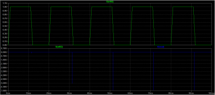
Across the top, you can see the voltage that gets applied to the voltage controlled switch. Across the back, you see large negative spikes in voltage. Really large. We see spikes of nearly 7 megavolts. Pretty amazing, from a 3.6 volt supply! This simulation may be overly optimistic: after all, it doesn’t take into account the stray resistance and capacitance that are likely to be present. But clearly Atdiy’s real life test indicates that high voltages are being developed.
In real life applications where inductive loads might be connected and disconnected quickly to varying loads, it’s common to use diodes to protect the remaining circuit from these high voltage spikes. We can do that in our simulated circuits too. Let’s add a pair of diodes to shunt both positive and negative voltages to zero (I picked 1N4158 diodes, somewhat arbitrarily):
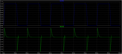
They do their job, check out the voltages:
Neat!
Flashback: the DEC 1091 at the University of Oregon
In my previous post, I mentioned that I had programmed a machine that used core memory. It was the DEC 1091 we had at the University of Oregon back in the mid 1980s. I was overcome with a feeling of nostalgia, and decided to try to look up how to install TOPS-10 onto the simh emulator.
Here’s a link, so I don’t forget it later.
Magnetic core memory reborn… on an Arduino????
I may have mentioned before, I’m kind of old. One measure of how old I am is the fact that I’ve actually programmed machines that used core memory. Real core memory. Little ferrite donuts on arrays of wires.
Some time ago, I remember running across this awesome blog post from “Wayne’s Tinkering Page” which showed some experimentation in creating a driver for some surplus 1mm ferrite memory cores, effectively creating a single bit memory. I thought that was pretty darned cool. But what’s even more amazing is what Ben North and Oliver Nash have done: create a 32 bit core memory shield for an Arduino.
Links to the report and board plans, bill of materials and software
And they have an excellent report on the project, which includes a reference to a different core memory technique which employed non-destructive reads.
Very cool.
Simulating the Joule Thief with LTSpice
I always think it is good to follow up a practical build of an electronic circuit with some simulation to try to learn some of the underlying design principles. LTSpice is a great circuit capture/simulation system which runs on Windows, but also runs pretty well under Wine. I was a bit intrigued by the behavior I noticed in my video: while the LED lit quite well using a single AA battery with a nominal 1.5 volts, when I connected the circuit to an old, partially depleted lithium coin cell that I extracted from a burned out “throwie”, it did not light my LED despite being measured at a nominal 1.4v or so. I thought this was pretty interesting. I had an idea about what the problem was, so I thought I’d test it in LTSpice.
Warning: I don’t know what I’m doing. That’s why I am doing what I am doing.
Here’s the schematic that I entered:
I determined the value of the inductors (44uH) using an online toroid calculator, specifying an FT-50-43 toroid with 10 turns through it. The K1 statement creates a transformer out of L1 and L2, with a coupling coefficient of 0.99 (just a guess, they are wound on the same toroid, I expect it to work rather well). In the circuit as presented, the battery is represented by the voltage source V1 and the resistor labelled ESR. From a data sheet for EverReady AA batteries, I found that the typical series resistance is somewhere between 150 and 300 milliohms. I picked an LED out of LTSpice’s catalog: no attempt was made to ensure it was close to the random LED I grabbed from my junkbox.
If you simulate it for a half a millisecond, and look at the voltage at Vout, you get the following graph:
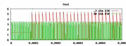
If you change the ESR to 30 ohms, and look at the voltage
Here’s a graph comparing them:
We can see that the voltage going into the LED peaks much higher, and remains higher for a significant period longer when supplied with a battery with a lower ESR. Using the FFT function, we can determine that the fundamental frequency is around 64Kh, and we can see that the average current is around 35 ma (a bit higher than the recommended average power for the LED, but not tremendously high, given the high frequency at which it operates).
When we have a 30 ohm resistance, the average current through the LED drops to a mere 3.5ma. While the voltage does appear to peak higher than the forward voltage needed to light the LED, the current supplied is simply too short and too low to significantly light the LED.
This seems to verify my experiments to a degree. But last night, I thought of this, and thought that perhaps I could boost the ability of these coin cells by paralleling them with a capacitor. I yanked out an electrolytic of around 220uF from my junk box, and wired it in parallel with the coin cell. The LED did light, but at a very low frequency, just a couple of Hertz. If I add a similar cap to my simulation, I don’t get this behavior. Not sure what’s going on. Any real engineers in the audience care to school me onwhy what I did here is completely inaccurate/wrong/stupid?
The Joule Thief — Lighting an LED with 1.5 volts
I was bored, but not quite up to the challenge of debugging my existing radio project, or starting a new one. I idly began winding some wire onto a FT-37-43 toroid, and then remembered that I had never constructed a “Joule Thief”, a simple little circuit that allows you to light an LED using just a 1.5 volt cell.
YouTube – The Joule Thief — Lighting an LED with 1.5 volts.
Addendum: I mentioned that legendary hacker Jeri Ellsworth had mentioned this circuit in one of her videos: I dug around and found the video. Her circuit is nearly identical, but adds a few components to implement a simple charging circuit.
I also did some experimentation with LTSpice to figure out why the lithium coin cells I scrounged from our old “throwies” didn’t light the circuit, even though they still measured 1.5v. It appears that these coin cells might have significant series resistance (perhaps as much as 30 ohms) compared to the much lower value for alkaline batteries (a nominal 150 to 300 milliohms, according to one datasheet I found). This appears to keep the transistor from supplying sufficient current to switch. I experimented with placing a capacitor across the coin cell (various values, from 33uF to 220uF electrolytics) and found that this did cause the LEDs to blink, but at a very low rate (with a 220uF, about 1Hz). I’ll try to follow up this post with one showing LTSpice and its simulation.
Ugly is Better
So, over the weekend I assembled the HamCan, and got some pretty wonky performance. I’m going to go through it all again and see if I can figure out why the receive performance is so bizarre, (loose connection? poor adjustment?) but it got me thinking that part of the issue is that typical PCB construction doesn’t really offer much advantage for prototyping. The boards are small. They don’t allow much room for experimentation, substitution and even debugging. My early experiments with so-called “ugly construction” like what I used for the FM transmitter I built last month worked much better. The technique is not optimized for mass production, but for individual experimentation and easy substitution and testing. That seems to be a very good thing.
So, my intention is to start an “Ugly Weekender”: one of Wes Hayward’s classic QRP designs. I’ve got a box set aside where I can start putting out the components I need (I should have most of them already, some of the variable caps might require a bit of substitution or creativity). But rather than just diving in, I think I am going to try to plan out the layout of each of the two/three boards it will cover, and consider modeling portions of the design in LTSpice. I’ll try to cover each step of this construction with videos and additional files that might be of use for someone considering a similar homebrew project. I’m in no hurry to get this done: it’s a project which is designed to maximize my own learning and enjoyment, so be patient (and encouraging, it really does help).
In the mean time, here are a couple of YouTube videos that serve as inspiration for this project.
Addendum: The original Ugly Weekender transmitter appeared in the August 1981 issue of QST in an article by Roger Hayward and Wes Hayward. The receiver appeared in the June 1992 issue in an article by Roger Hayward. Both are available to ARRL members through their excellent online archive of QST backissues.
Today’s Project: The HamCan
I ordered a little HamCan kit about a week ago. It’s a little QRP CW transceiver produced by the Four State QRP kit. Today, I spent about an hour assembling it, and fired it up. This is just a short status report: it’s acting a bit wonky. The tone sounds pretty rough, the frequency seems off, and adjusting the regeneration doesn’t seem to change anything. I’ll be debugging it over the next week or so, but consider this a quick little intro to it.
Addendum: Here’s the radio hooked up and “working”. If anyone has any bright ideas on how to debug it, feel free to drop me an email with your suggestions.
Astronomical Musings: What day is Pixar-Henge day?
I’ve had a couple of conversations with Tom over the last couple of days, and they were curiously related. He just got back from a trip to Ireland where he visited Newgrange, a prehistoric tomb mound in County Meath. It actually predates the Great Pyramid at Giza, and predates Stonehenge by a thousand years.
One of its interesting feature is that on the date of the winter solstice, the rising sun illuminates the entire length of the main passage, providing 17 minutes of light to the inner chamber. Pretty neat. A lottery is apparently held each year for tickets to view this event (thousands apply, a couple of dozen are allowed to view).
Anyway, in a separate conversation, Tom announced that today, a similar event happened at Pixar. Our main building has a long corridor that runs east to west, and apparently this morning (May 6) was the date in which the rising (and setting) sun appears at the eastern (western) end of the corridor, and illuminates the entire hall.
So, Tom asked: “What’s the equivalent date when we can view this event again?”
A few minutes of thought told me that however many days we are away from the summer solstice, I could solve that if I could do add and subtract dates in my head, or by counting dates on a calendar, but I decided to use the pyephem library instead. I didn’t even write a program:
> python
Python 2.6 (r26:66714, Mar 17 2009, 11:44:14)
[GCC 4.4.0 20090313 (Red Hat 4.4.0-0.26)] on linux2
Type "help", "copyright", "credits" or "license" for more information.
>>> import ephem
>>> t = ephem.Date('2011/05/06')
>>> s = ephem.Date('2011/06/21')
>>> print ephem.Date(s+(s-t)*ephem.hour*24)
2011/08/06 00:00:00
In other words: the alternative “Pixar-Henge” day is August 6.
But what angle is our hallway aligned? For that., I fired up Google Earth, and used their measurement tools. Assuming that the long hallway runs parallel to the long side of the building, I determined that the length of our building was approximately 140 meters, and was at an angle of 75.22 degrees.
But here is the thing: I then did the calculation on pyephem to see what direction it thought the rising sun would be: and it came up with 68 degrees. That just seems wrong. Not sure what to think here. I’ll ponder it some more.
Word squares…
I like to read the Programming Praxis website. Every post challenges you to write some simple programs to boost your skill, akin to finger exercises for a musical instrument. Today’s challenge was an interesting which intrigued Charles Babbage: creating word squares.
I spent about 10 minutes writing one in Python that worked rather well: here is an early version, which I augmented a bit. Running it against /usr/share/dict/words gave way too many squares, with lots of really uncommon words. I had better luck with The 12dicts word lists, which concentrate on more common words. In particular, I came up with this pair of rather pleasing order 5 squares based upon the words BRAIN WAGON.
|
|
Fun!
A small standalone homebrew computer: FIGnition by Libby8dev
I’m old. I learned to program as a teenager in the 1980s. Back then, we learned to program on small microcomputers. These machines weren’t very powerful, but they had a neat feature: they were self-hosted. In recent years, a large variety of small microcontrollers have become popular. Many of these have capabilities far in excess of what we had back then, but almost without fail the programming environments they use are hosted on much more powerful machines, often using code which measures tens or hundreds of megabytes.
That has always seemed a bit excessive to me, particularly since making the environments simple and self-hosted pays benefits for educational and hobbyist applications.
The FIGnition board is a project which seems to combat this trend:
FIGnition is an educational DIY computer, based around an Atmel AVR microcontroller. It uses 3 chips and only 46 components to provide a complete self-hosted computer with 8Kb of RAM; 384Kb of storage space; an 8-key keypad and PAL video output. It is interfaced and powered by USB and uses V-USB to provide firmware upgrades by implementing a usbasp device. It runs a variant of FIG-Forth.
Currently it isn’t available in the US since it doesn’t do NTSC video, but I suspect that will change soon. I’ll be looking back at this project periodically.
