Daily Archives: 7/29/2011

On the Ham Nation podcast, or the perils of perpetual promotion.

Ham Nation is a relatively new weekly podcast that is brought to us through the power of the TWIT network, Leo Laporte’s mighty podcast empire. Fellow blogger KE9V had some comments on it, some of which I agree with, and some of which I do not.

Of Dits and Bits | KE9V’s Ham Radio Blog.

First, the positives. Hosts Bob Heil and Gordon West are practically legends in the world of ham radio. Both are charming gentlemen, deeply concerned with promoting ham radio.

And in a strange sort of way, that’s what I find to be most disconcerting about the show. It tries really, really hard to convince you that ham radio is exciting and relevant. I do firmly believe it’s a great hobby. Or more precisely, it’s a bunch of great hobbies, all united under the need to get a license to operate. Some aspects of the hobby I like better than others. I can appreciate that other people might like aspects of the hobby that I do not. I can also appreciate that some people might want to promote the hobby.

But I can’t help but think that we overstep our promotion of ham radio sometimes. In trying to understand why I feel that way, I see two primary causes.

First, in our haste to bring new people into the hobby, we try to talk about ham radio in a way that the uninitiated can understand. That’s okay, but unless we are careful, we end up never talking about anything else. And frankly, I see that a lot in the first ten episodes of Ham Nation. Like KE9V, I haven’t seen that there is anything being presented in Ham Nation that anyone whose been in the hobby for more than a year will care about. In an effort to make the hobby understandable to the layman, we are stripping out everything interesting from our hobby. We are providing no inspiration to deeper achievement in ham radio. We perpetually talk about what equipment to buy, but never talk about the equipment we build. We promote simple wire antennas, without working to provide information on more complex and therefore higher performing antenna systems. And Ham Nation has this in spades. It’s not too surprising: Gordon West has made a career out of selling study aids for ham radio and getting new people into the hobby. But I can’t help but wish that there was a podcast that actually talked about ham radio in a way that at least periodically reached beyond how to solder and your first wire antenna.

Second, there is the idea that ham radio is unique among hobby in promoting virtue and intellectual development. Most hams are great people, but I believe that most people are great people. There are some really amazingly intelligent people in ham radio, but there are intelligent people in all walks of life, with all sorts of hobbies. I suspect that if your hobby was windsurfing, most of your fellow windsurfers would be good, intelligent people too. The difference is that windsurfers don’t spend a lot of time trying to convince you that windsurfers are really great people. They just accept that if you want to be a windsurfer, you’ll learn what you need to, and you’ll join a great group doing something they love. Hams want to convince you that they are a bunch of great guys, doing great stuff, but they seem to spend all their time talking about how great they are, and relatively little time showing you how great they are.

Ham Nation suffers from both of these ills.

It’s not enough to have celebrity hams. It’s not enough to tell everyone how great ham radio is and how much they will love it and how easy it is. You have to get on with doing ham radio, to demonstrate how cool you think it is, and let other people make up their own minds. When people like Kevin Rose express skepticism about the hobby, we shouldn’t tell him he is wrong: we should show him he is wrong. And we should accept that perhaps he isn’t wrong, at least for him.

It’s just a hobby after all.

On RC Filters…

Over on the #savagecircuits IRC channel on irc.afternet.org, Atdiy was trying to decipher the mysteries of a mainstay of analog circuit design: the RC filter such as the one pictured on the right (diagram cribbed from Wikipedia) It dawned on me that (newbie as I am) I didn’t really have a clear understanding of them either, so I thought it would be worth the exercise to go through the mathematics of them as well, and try to derive the simple formulas from (more or less) first principles.

First of all, it’s interesting to just try to understand what happens at DC voltages. No current flows through the capacitor at DC, so the output voltage is just the input voltage (when measured as an open circuit, more on this later). If you are a total newbie like me, you can look at the capacitor symbol, and note that one side is not connected to the other (it’s an open circuit), so no current can flow across it (at least, at DC) frequencies. But at higher frequencies, we need to consider the behavior of the capacitor, which means that we need to consider impedance.

If you don’t grok complex numbers, the road ahead will be a tiny bit bumpy. I didn’t have enough brain power to write an intro to complex arithmetic, but if it’s new to you, consider reading up on it. For now, just remember that complex numbers can be manipulated like regular numbers (adding, multiplying,dividing and the like) but have different rules.

Rather than derive anything at this point, we’ll just cheat a tiny bit and introduce a formula to find the reactance of the capacitor. (You should not feel too uneasy at this point by introducing what seems like magic at this point. The following equation just describes how capacitors work. You probably accepted that resistors could be described by a single number (expressed in ohms). Because capacitors have more complicated behavior in AC circuits, they need a bit more complicated description, but not too much).

The capacitive reactance of the capacitor is given by:

[latex]X_C = \frac{1}{2 \pi f C}[/latex]

where [latex]f[/latex] is the frequency of operation, and [latex]C[/latex] is the capacitance in farads (be careful, not microfarads). For instance, a 1 nanofarad capacitor has a reactance of about 160 Ohms at 1Mhz.

I glossed over something a bit there. The reactance we computed is measured in ohms, which makes it seem like it’s a resistance. But in reality, it’s an impedance (usually written as the symbol [latex]Z[/latex]). Impedance is a measure of the opposition of a circuit to current, but it generalizes resistance by taking into account the frequency dependent behavior of capacitors and inductors. In particular, impedance varies with frequency.

You can split the impedance into the sum of two parts, the pure resistance (usually written as [latex]R[/latex]) and the reactance (usually written as [latex]X[/latex], as we did above when we were computing the reactance of the capacitor). The total reactance of a circuit is the inductive reactance minus the capacitive reactance. If the overall reactance is negative, the circuit looks like a capacitor. If the sum is positive, it looks like an inductor. If they precisely cancel, then the reactance disappears, and the circuit presents no opposition to current at all.

But how do we handle resistance? Here’s where the complex numbers come in.

[latex]Z = \sqrt{R^2 + X^2}[/latex]

[latex]X = X_L – X_C[/latex]

The nifty bit is that you can treat impedances exactly as if they were resistances (e.g. we can use Ohm’s law) just so long as we remember that we are dealing with complex quantities. I decided to write a small Python program which could be used to compute the filter responses of RC filters:

#!/usr/bin/env python
#
# Here is a program that works out how RC filters
# work.  Here is a diagram of the prototypical 
# RC low pass filter, sampled across a resistive
# load Rload.
#
#              R                
# Vin ->  ---/\/\/\/\----+--------+ Vout
#                        |        |
#                        |        /
#                        |        \
#                    C -----      /  Rload
#                      -----      \
#                        |        /
#                        |        \
#                        |        |
#                      -----    -----
#                       ---      --- 
#                        -        -  

import math
import cmath

RLoad = 1e9
R = 600                 #
C = 0.0000001           # .1uF

for f in range(10, 100000, 10):
        XC = complex(0., -1/(2.0*math.pi*f*C))
        Z = cmath.sqrt(XC*XC)
        t = RLoad * Z / (RLoad + Z)
        Vout = t / (R + t)
        print f, 20.0 * math.log10(cmath.sqrt(Vout*Vout.conjugate()).real)

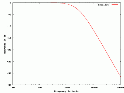
If you take the data that gets printed out here and graph it, you get the following:

I built the same circuit in LTSpice just to check my understanding, and the graph appears identical. If you search through the data to find the place where the response drops to -3db, you find it occurs around 2650 Hz. The traditional formula for filter bandwidth is

[latex]F = \frac{1}{2 \pi R C}[/latex]

which when you plug in the values I chose, you end up with 2653.9 (which is pretty good agreement).

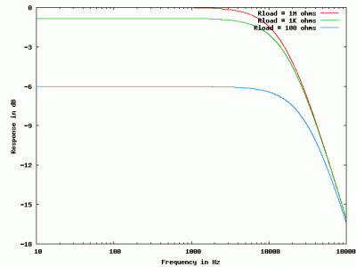
Addendum: This filter works best when the input impedance is very low (compared to the 600 ohms that we chose for the input resistor [latex]R[/latex]) and where the load impedance [latex]Rload[/latex] (here purely resistive, but it could also be complex) is high. If the load were low (Rload was comparable or less than than R) then the losses would be higher. (Ignore the capacitor. If Rload is small compared to R, then the voltage, even at DC, is already divided down to a lower value, this shifts the entire curve downward).

Addendum2: I wrote this hastily. If it doesn’t make sense, or people have suggestions, don’t hesitate to add them in the comments below.

Addendum3: Atdiy asked me to run some simulations showing how the load [latex]Rload[/latex] changes the output to demonstrate loss. Here, I kept [latex]R = 100[/latex], but varied [latex]Rload[/latex] from 1M ohms, to 1Kohms, and then down to just 100ohms. You can see the entire curve moves down, with only 100 ohms of load resistance, the voltage is -6db (multiplied by 0.25) even at DC).

Addendum4: Atidy has started her series on filter design, which includes a qualitative description of how these filters work that you might find easier to understand. Check it out here.
.

PDP-10/X on an FPGA

I think I saw this a couple of years ago, but Doug Conroy seems to have made some progress on his implementation of a PDP-10 on an FPGA. It now can apparently boot ITS. I’m more interested in the prospect of running TOPS-10 so I can relive my early days, but booting ITS is pretty awesome. Bookmarked for later retro-geek-hacking-envy:

PDP-10/X.