I recall burning three or four weeks of a sabbatical getting Saccade.com on the air with Wordpress. So much tweaking…
KD1JV on boost and buck converters implemented with an ATtiny13V
Legendary QRP hacker Steve “Melt Solder” Weber has some awesome stuff on his website, particularly if you are interested in homebrew ham radio gear. (Indeed, it appears he’s about ready to offer his legendary ATS-4 5 band rig kits again, experienced kit builders might want to check it out.) But what drove me to his website this morning is quite clear exposition of buck and boost voltage converters in PDF form. Remember my ATtiny13 powered Halloween pumpkin? It was inefficient: about half of the power consumed in the circuit was simply lost as heat in the current limiting resistor. Had I read Steve’s exposition a month out from Halloween, I might have tried to do better.
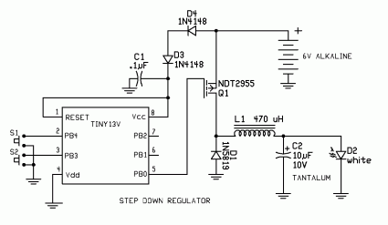
Here’s the relevent circuit cribbed from his PDF:
Pretty simple! A couple of things to note: the NDT2955 is a logic level P type MOSFET, which turns fully on with a gate threshold of just 4V. Readers may remember that my own experiments with the IRF510 didn’t succeed in some small part because the IRF requires 10V to switch entirely on. Secondly, the ATtiny13 is powered directly from a 6V supply, through two diodes. These are there simply to drop the voltage to the 5.5V level which is the maximum safe amount. The ATtiny13V is very forgiving on voltages, and can operate all the way down to 1.8V, long after the batteries will have given up the vast majority of their power.
I’ll try to work through the equations and design a similar driver for my 1W Cree LEDs. To build it, i’ll need to come up with an appropriate MOSFET. Stay tuned.

Comment from mahesh joshi
Time 1/13/2016 at 12:50 pm
Dear sir
can you help me
plz provide ic number
i have require two ccp in 8pin ic