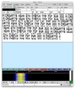
 Update: Welcome Hack-a-day readers! If you are looking for the schematics for this “transmitter” (really just a simple oscillator, send some love to radio guru Steve Weber over at his website. You could really use any oscillator you like, even a canned oscillator (although the square waves would generate lots of harmonics).
Yesterday’s project coupled a simple Colpitt’s oscillator (snipped from Steve Weber, KD1JV) with an Arduino. Steve used it to send temperature telemetry in Morse code back to his shack from an outdoor thermometer. But I thought that something else could be done: sending telemetry in Hellschreiber.
Hellschreiber is an early type of facsimile teleprinter system developed in the 1920s, which has enjoyed a certain amount of popularity in the amateur radio community. It sends characters using a conventional on-off keyed transmitter, just like Morse, but instead of sending dots and dashes of different lengths, it scans characters left to right, and top to bottom, and keys the transmitter on where each letter is “on”. Thus, a Morse transmitter can be modified pretty simply to send Hellschreiber.
So I did.
Here are some details. Hellschreiber is normally defined as sending characters defined on a 7×7 matrix, at 122.5 dots (2.5 characters) per second. But the actual font is actually defined on a 7×14 matrix. To keep the bandwidth of the signal down, the font doesn’t ever define a character that requires turning single dots on or off: the minimum signal changes are two dots long. These “half dots” are sent at 245 baud, or about 4.08ms per dot. Because I needed to account for the time spent looking up the character, I tuned that down to about 4.045ms. I was concerned that because I was keying the oscillator on and off, the startup time (which I estimated at about 2ms) could be a problem, but I suspect the shutdown time is about 2ms as well, so the overall system works better than you might imagine. The startup and shutdown keying waveforms are a bit erratic though, and the bandwidth of the signal is probably too wide. I think a better way to do this would be to build an oscillator that runs continuously, and then key a buffer amp with a filtered pulse to keep the bandwidth low. But for a 500 microwatt transmitter (estimated, and represents power going into the antenna, not radiated) it probably works just fine.
Here’s the source code:
[sourcecode lang=”cpp”]
int radioPin = 13 ;
typedef struct glyph {
char ch ;
word col[7] ;
} Glyph ;
Glyph glyphtab[] PROGMEM = {
{‘ ‘, {0x0000, 0x0000, 0x0000, 0x0000, 0x0000, 0x0000, 0x0000}},
{‘A’, {0x07fc, 0x0e60, 0x0c60, 0x0e60, 0x07fc, 0x0000, 0x0000}},
{‘B’, {0x0c0c, 0x0ffc, 0x0ccc, 0x0ccc, 0x0738, 0x0000, 0x0000}},
{‘C’, {0x0ffc, 0x0c0c, 0x0c0c, 0x0c0c, 0x0c0c, 0x0000, 0x0000}},
{‘D’, {0x0c0c, 0x0ffc, 0x0c0c, 0x0c0c, 0x07f8, 0x0000, 0x0000}},
{‘E’, {0x0ffc, 0x0ccc, 0x0ccc, 0x0c0c, 0x0c0c, 0x0000, 0x0000}},
{‘F’, {0x0ffc, 0x0cc0, 0x0cc0, 0x0c00, 0x0c00, 0x0000, 0x0000}},
{‘G’, {0x0ffc, 0x0c0c, 0x0c0c, 0x0ccc, 0x0cfc, 0x0000, 0x0000}},
{‘H’, {0x0ffc, 0x00c0, 0x00c0, 0x00c0, 0x0ffc, 0x0000, 0x0000}},
{‘I’, {0x0ffc, 0x0000, 0x0000, 0x0000, 0x0000, 0x0000, 0x0000}},
{‘J’, {0x003c, 0x000c, 0x000c, 0x000c, 0x0ffc, 0x0000, 0x0000}},
{‘K’, {0x0ffc, 0x00c0, 0x00e0, 0x0330, 0x0e1c, 0x0000, 0x0000}},
{‘L’, {0x0ffc, 0x000c, 0x000c, 0x000c, 0x000c, 0x0000, 0x0000}},
{‘M’, {0x0ffc, 0x0600, 0x0300, 0x0600, 0x0ffc, 0x0000, 0x0000}},
{‘N’, {0x0ffc, 0x0700, 0x01c0, 0x0070, 0x0ffc, 0x0000, 0x0000}},
{‘O’, {0x0ffc, 0x0c0c, 0x0c0c, 0x0c0c, 0x0ffc, 0x0000, 0x0000}},
{‘P’, {0x0c0c, 0x0ffc, 0x0ccc, 0x0cc0, 0x0780, 0x0000, 0x0000}},
{‘Q’, {0x0ffc, 0x0c0c, 0x0c3c, 0x0ffc, 0x000f, 0x0000, 0x0000}},
{‘R’, {0x0ffc, 0x0cc0, 0x0cc0, 0x0cf0, 0x079c, 0x0000, 0x0000}},
{‘S’, {0x078c, 0x0ccc, 0x0ccc, 0x0ccc, 0x0c78, 0x0000, 0x0000}},
{‘T’, {0x0c00, 0x0c00, 0x0ffc, 0x0c00, 0x0c00, 0x0000, 0x0000}},
{‘U’, {0x0ff8, 0x000c, 0x000c, 0x000c, 0x0ff8, 0x0000, 0x0000}},
{‘V’, {0x0ffc, 0x0038, 0x00e0, 0x0380, 0x0e00, 0x0000, 0x0000}},
{‘W’, {0x0ff8, 0x000c, 0x00f8, 0x000c, 0x0ff8, 0x0000, 0x0000}},
{‘X’, {0x0e1c, 0x0330, 0x01e0, 0x0330, 0x0e1c, 0x0000, 0x0000}},
{‘Y’, {0x0e00, 0x0380, 0x00fc, 0x0380, 0x0e00, 0x0000, 0x0000}},
{‘Z’, {0x0c1c, 0x0c7c, 0x0ccc, 0x0f8c, 0x0e0c, 0x0000, 0x0000}},
{‘0’, {0x07f8, 0x0c0c, 0x0c0c, 0x0c0c, 0x07f8, 0x0000, 0x0000}},
{‘1’, {0x0300, 0x0600, 0x0ffc, 0x0000, 0x0000, 0x0000, 0x0000}},
{‘2’, {0x061c, 0x0c3c, 0x0ccc, 0x078c, 0x000c, 0x0000, 0x0000}},
{‘3’, {0x0006, 0x1806, 0x198c, 0x1f98, 0x00f0, 0x0000, 0x0000}},
{‘4’, {0x1fe0, 0x0060, 0x0060, 0x0ffc, 0x0060, 0x0000, 0x0000}},
{‘5’, {0x000c, 0x000c, 0x1f8c, 0x1998, 0x18f0, 0x0000, 0x0000}},
{‘6’, {0x07fc, 0x0c66, 0x18c6, 0x00c6, 0x007c, 0x0000, 0x0000}},
{‘7’, {0x181c, 0x1870, 0x19c0, 0x1f00, 0x1c00, 0x0000, 0x0000}},
{‘8’, {0x0f3c, 0x19e6, 0x18c6, 0x19e6, 0x0f3c, 0x0000, 0x0000}},
{‘9’, {0x0f80, 0x18c6, 0x18cc, 0x1818, 0x0ff0, 0x0000, 0x0000}},
{‘*’, {0x018c, 0x0198, 0x0ff0, 0x0198, 0x018c, 0x0000, 0x0000}},
{‘.’, {0x001c, 0x001c, 0x0000, 0x0000, 0x0000, 0x0000, 0x0000}},
{‘?’, {0x1800, 0x1800, 0x19ce, 0x1f00, 0x0000, 0x0000, 0x0000}},
{‘!’, {0x1f9c, 0x0000, 0x0000, 0x0000, 0x0000, 0x0000, 0x0000}},
{‘(‘, {0x01e0, 0x0738, 0x1c0e, 0x0000, 0x0000, 0x0000, 0x0000}},
{‘)’, {0x1c0e, 0x0738, 0x01e0, 0x0000, 0x0000, 0x0000, 0x0000}},
{‘#’, {0x0330, 0x0ffc, 0x0330, 0x0ffc, 0x0330, 0x0000, 0x0000}},
{‘$’, {0x078c, 0x0ccc, 0x1ffe, 0x0ccc, 0x0c78, 0x0000, 0x0000}},
{‘/’, {0x001c, 0x0070, 0x01c0, 0x0700, 0x1c00, 0x0000, 0x0000}},
} ;
#define NGLYPHS (sizeof(glyphtab)/sizeof(glyphtab[0]))
void
encodechar(int ch)
{
int i, x, y, fch ;
word fbits ;
/* It looks sloppy to continue searching even after you’ve
* found the letter you are looking for, but it makes the
* timing more deterministic, which will make tuning the
* exact timing a bit simpler.
*/
for (i=0; i<NGLYPHS; i++) {
fch = pgm_read_byte(&glyphtab[i].ch) ;
if (fch == ch) {
for (x=0; x<7; x++) {
fbits = pgm_read_word(&(glyphtab[i].col[x])) ;
for (y=0; y<14; y++) {
if (fbits & (1<<y))
digitalWrite(radioPin, HIGH) ;
else
digitalWrite(radioPin, LOW) ;
delayMicroseconds(4045L) ;
}
}
}
}
}
void
encode(char *ch)
{
while (*ch != ‘\0’)
encodechar(*ch++) ;
}
void
setup()
{
Serial.begin(9600) ;
pinMode(radioPin, OUTPUT) ;
}
void
loop()
{
encode("K6HX QTH CM87UX TMP 72F PWR 500 MICROWATTS ") ;
}
[/sourcecode]
Let me know if you use this project for anything!