As my recent video showed, I have a lot of development boards. I also have a fair number of little boards that are useful to plugin to these development boards to accomplish various tasks. Yesterday, I received a little OLED board that I thought I’d try hooking up and let you know about my experience.
There are lots of boards out there that apparently use the same screen: a 0.96″ OLED display with a resolution of 128×64. I ordered this one from Amazon for only $9 with free shipping. The description is a little bit misleading: you can find versions of these kinds of boards that have 7 or 8 pins and use the SPI bus. This one has (and requires) only four pins, and uses the I2C bus. I’m no expert on the technical differences, but my general impression is that SPI is full duplex and can run at higher speed and at longer range, but requires individual chip select lines for each device, where the I2C bus uses chip addressing, so no additional wires need to be hooked up to select the proper target device. (If any of my genius readers care to correct me on that, feel free to leave a comment).
Here’s a picture of the module I got, as I tweeted it yesterday:
New OLED display…. pic.twitter.com/8B27BIOFXl
— Mark VandeWettering (@brainwagon) March 16, 2015
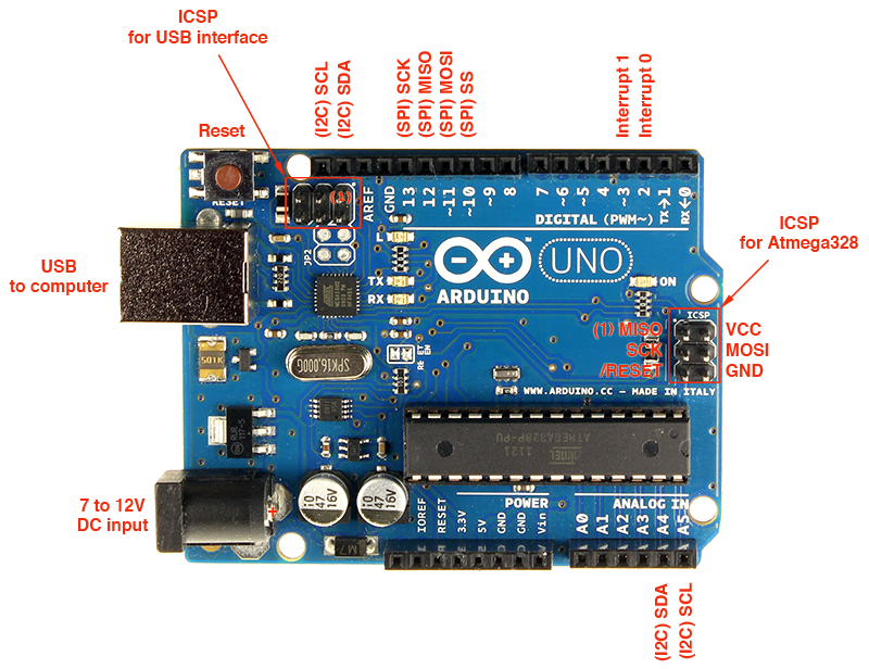
It’s safe to run on either 5v or 3.3v, without any level converters or other nonsense. I hooked it up to one of my Sparkfun RedBoard Arduino clones. I plugged it into a bread board, and then wired up the four connections. VCC goes to the 5V pin on the Redboard, GND goes to one of the Arduino grounds. The remaining two lines need to be hooked up to the SCL (serial clock) and SDA (serial data) lines on the Arduino. This caused me a minor bit of confusion: on an Arduino R3, those two pins are on A4 and A5.
On the RedBoard, these pins are split out separately onto separate pins near the AREF pin.
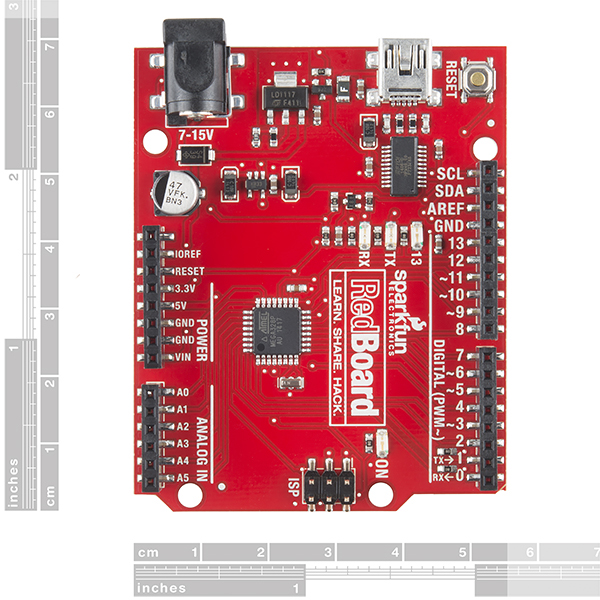
I connected them to the SCL/SDA connectors on the RedBoard. I suspect that on the Uno R3, A4/A5 are the connectors you’ll need. Other variants of the Arduino might need different pins.
And, of course you’ll need some software. It’s tempting to go to Adafruit for all things Arduino, but in this case it can be a bit of a mistake I think, or at least it might require a bit of tinkering. Adafruit sells their own OLED boards, but they are a bit more costly and are wired a bit differently, and I thought that might make their software a little trickier to configure.
Instead, I found the U8G graphics library. It’s fairly nice because it supports a wide variety of boards, and is self contained. If you download the Arduino code and unzip it into the Arduino library directory and restart the Arduino environment, you’ll see some examples installed. But if you load one and try to compile it, you’ll encounter an error: the examples aren’t configured for the particular board you need. To do that, you need to uncomment the right definition for the graphics device.
For this specific device, you want to delete the two slashes at the start of this line. This selects the I2C bus, and tells it to use the SSD1306 chip that is on the board. This one worked for me.
//U8GLIB_SSD1306_128X32 u8g(U8G_I2C_OPT_NONE); // I2C / TWI
So, I downloaded the “Graphics Test” example, made that modification, compiled it and downloaded it to the RedBoard. Voila
A pretty neat little display. I must say that it’s a bit too tiny for my old-guy eyes to read when the print is small (damn you presbyopia!) but It’s very sharp and clear. If you have need of such a device, this one seems inexpensive and easy to use. Check it out.