Monthly Archives: April 2015

Help wanted for new project… The Big Box O’ RF

As I’ve mentioned over the last few months, I have piles of different development boards, and lots of little display modules and the like. I’ve been thinking of doing a simple radio project, aimed at helping further experimentation with QRP (low-power) radio homebrewing. Inspired by Pete and Bill over at the Soldersmoke Podcast, I thought that I might use a dev board to build a gadget which I am calling:

The Big Box O’ RF

The idea is to take an Arduino (or maybe Teensy?), and connect a couple of different peripherals to it that can generate RF. I have both an AD9850 DDS module:

ads9580

And one of Adafruit’s Si5351 boards, which are cool because they can generate three different outputs at once, under I2C control:

2045-00

I also have one of Jason’s (NT7S) little Si5351 kits that I could assemble:

Si5351ABB-Assembled-Large.500

And of course I have a bunch of I2C display peripherals, some rotary encoders, and various power jacks. All I really need would be a nice aluminum box, and I could assemble a general purpose signal source/VFO that I could use in experiments.

Sounds pretty cool, yes?

Well, I have a few details to work out:

  • I’m envisioning a front panel which has a bunch of panel mount connectors that I can attach coax pigtails to route RF to my various project. (Probably 4, one for the AD9850, and three for outputs from the Si5351). The (semi) obvious choice would be SMA female panel connectors, and use pigtails to inject the RF into various other projects. Does anyone have any recommendations for where to get reasonably inexpensive SMA male-male pigtails? Is there a better (read cheaper) alternative that could be used? I’ve used Type F or even RCA jacks before, is that stupid?
  • Inside the box, would you use RG174 or RG316 to carry RF signals from the board outputs to the panel mounts? Any hints on shielding?
  • Should I make a buffer amplifier for the outputs? Or low pass filter modules (switchable?)

This project doesn’t need to be perfect, but it would be nice if it was good enough to serve as test equipment that I would want to keep on my desk. Anybody have any ideas?

Addendum: This box built by Bob, WV2YAU seems close to what I have in mind:

An Arduino by any other name…

I was trying to make some headway on my robotic platform project, so I went digging through boxes in my office to find the large, 12v SLA battery that I know I have somewhere. While searching I found a bunch of stuff: hundreds of red LEDs in a pack, two Arduinos, a Sparkfun breakoutboard for an electret microphone, a bunch of level converters, and a Teensy 3.0. But of course, no battery.

So, I played a bit with the Teensy.teensy

The Teensy 3.0 is an older version of the more modern Teensy 3.1 and the Teensy LC (which I have on order right now from Sparkfun). It’s a, well, teensy board: only 1.4″ x 0.7″ It has a 32 bit arm processor which has 128K of flash and 16kb of RAM, and a bunch of peripherals. You have to solder on your own header pins, but it would be easy to do so and put it on a breadboard. And, what’s sort of cool, you can program it pretty much exactly like an Arduino. Same setup()/loop() structure. You use pinMode(), digitalRead() and digitalWrite(). The Serial objects work the same. Pretty cool.

As a first (but not particularly challenging) test, I downloaded my Morse beacon code. It worked fine, with no changes: the Teensy even uses pin 13 to flash its tiny onboard orange led. Pretty nifty.

I’ve been pondering using Arduino Mini/Nanos for future projects, but I’m kind of viewing the ATMega328 chip that underlies those Arduinos as a bit of a dinosaur. These chips are a lot faster, and at around $13 for the Teensy LC (which has same clock rate, but only 64K flash and 8K memory) I think I may have found a better embeddable CPU for projects.

Addendum: the Teensy family is well supported with platformio as well.

Interested in the history of my callsign: K6HX

I was originally licensed under the callsign KF6KYI (Kenwood-Yaesu-Icom, or what I prefer, Kiss Your Iguana) but when I upgraded to Extra a few years back, I dug around and was lucky enough to snag the callsign K6HX (missed out on getting the highly desirable K6TT, which would have been AWESOME). I never really gave it much thought. I remember looking up the history of the call, and finding that it was previously held by something called the “Lew Stoner Memorial DX Club”, with Donald Stoner, W6TNS listed as the club trustee. Both his call and the club call (along with a second one called the Lew Stoner Memorial DX Club East W8IMS) had expired, so I hypothesized that this gentleman had become a silent key, and nobody had stepped forward to claim his call or renew the club calls.

Tonight, I dug a little deeper, and found something interesting that I did not know.

No doubt some of you are familiar with Don. He is perhaps most famous for being the guy who first dreamed of the OSCAR: which stood for Orbiting Satellite Carrying Amateur Radio. He laid out a vision for the program in a February, 1961 article for QST magazine (if you are a member of the ARRL, you can download a copy). In it, he lays out the vision of a satellite beacon, and a later satellite repeater that could be operated and worked by radio amateurs on the 2m band. It’s a very cool article, and of course now 50+ years later, amateurs achieved all he dreamed of and more. In it, he mentions that he would publish the circuit for a beacon transmitter that could be built by amateurs for “less than $15”, but as near as I can tell, that article was never published.

But digging around a bit more, I found that Michael Rainey, AA1TJ, had posted an interesting article referring to a 1959 article by Don which detailed the circuit that was used by Vanguard 1. Michael has done a ton of cool stuff with old, vintage transistors, and details in his article a recreation of the original beacon circuit, which he cribbed from a 1959 article by, you guessed it, Don Stoner.

I was not able to find any references to “Lew Stoner” or to any activities by the DX Club which bears his name. Does anyone else know any more information?

Exciting AMSAT-NA opportunity…

I read this today:

AMSAT is excited to announce that we have accepted an opportunity to participate in a potential rideshare as a hosted payload on a geostationary satellite planned for launch in 2017. An amateur radio payload, operating in the Amateur Satellite Service, will fly on a spacecraft which Millennium Space Systems (MSS) of El Segundo, CA is contracted to design, launch, and operate for the US government based on their Aquila M8 Series Satellite Structure.

Complete Press Release Here

This would be very exciting. The only satellites I’ve worked have really worked with any regularity have been the FM satellites in low earth orbit. I’d love to have an opportunity to develop a station to work a bird in geostationary orbit. I’ll be watching this closely, and probably kicking in some donations to AMSAT-NA to grease the skids.

Monkeying around with the Lytro Camera…

A couple of people on my twitter feed yesterday (aside: I tweet using @brainwagon, and passed 5000 tweets yesterday) had questions about how this light field camera worked, how fast the sensor was, how long it takes to acquire the image, etc… While this is the first Lytro camera I’ve ever had the time to tinker with, I did spend a couple of years doing R&D on computational photography in general and light field photography in particular, so I am pretty familiar with how these things work, and combined with information like the Lytro Meltdown and the lfp splitter, I was able to tear apart my example the files for the example “monkey” picture I took yesterday. For completeness:


So, how does the Lytro take pictures that can do this?

First, let’s take a look at the cross section of the camera, thoughtfully provided from Lytro on the web:

lytro

Despite it’s kind of primitive outer appearance, inside it’s remarkably complex. As someone who played a small part in the optical design of a similar camera, it can be remarkably tricky. But you might look at it and say: “Gosh, it’s a telephoto lens, big whoop! Where is the ‘secret sauce’?”

It’s in the area labelled light field sensor. Instead of having an ordinary CCD which simply samples the illumination on the focus plane at a bunch of individual locations, the light field camera has a micro lens array: an array of tiny lenses which allow the camera to not only measure the total illumination arriving at a location, but it’s distribution: what proportion of that light is arriving from each direction. It’s this property that will eventually allow the computational magic allows refocusing.

You probably aren’t able to visualize that very well (I certainly couldn’t when I began), but here’s an example which may (but probably won’t) help a bit. Even if you don’t completely get it, it’s kind of cool.

Using the lfpsplitter tools above, I extracted the “raw” pixel data from the monkey snapshot I did. If you are familiar with the way most cameras work, you might know that inside digital cameras is a sensor which can be thought of as an array of pixels. Some are sensitive to red, some green, some blue, usually arranged in an grid that is called a a Bayer filter or a Bayer mask. Software in your camera is responsible for looking at each individual R, G, and B pixel and combining them to produce RGB pixels of a resolution lower (usually by 1/2) of the native resolution of the sensor. The image below is a similar “raw” image of the sensor data coming from the Lytro. It is represented as monochrome values, each of which is 16 bits. It looks dark because all the processing of the Bayer filtering, exposure, color balance etc has not been done. The original images are 3280×3280, which I’ve shrunk down to fit on this page.

Screen Shot 2015-04-25 at 9.10.30 AM

You can probably see monkey, but might ask, “again, what’s the deal? Seem just like a dark, bad image of the monkey?” Let’s zoom in.

Screen Shot 2015-04-25 at 9.10.44 AM

And further?

Screen Shot 2015-04-25 at 9.11.04 AM

And finally down at the bottom, looking at individual pixels:

Screen Shot 2015-04-25 at 9.11.15 AM

The large image is actually made up of little tiny circular images, packed in a hexagonal array. Each pixel is about 1.4 microns across. The circular images of each lenslet are about 13.89 microns across. The rectilinear “gridding” artifact you see is from the Bayer mask.

Pretty nifty.

The software that gets you from this raw image to the final image is actually non trivial, in no small part because the calibration is so difficult. But it’s awesome that I have a little gadget that can acquire these raw light fields (our prototypes were far bulkier).

Last night, I spent some time trying to understand the Wifi protocol, and wrote some code that was successful in receiving the callback messages from the camera, but had a bit more difficulty with understanding and getting the command messages to work. The idea is to create a set of Python programs that will allow me to pull this kind of raw data from the camera, without needing to go through the Mac OS/Windows Lytro Desktop software. If anyone has done this, I’d love to compare notes. Stay tuned.

Got a first generation (obsolete!) Lytro Camera…

I spent a couple years of my life working on a light field motion picture camera (and got named on two patents) as part of my former work, so I’ve been interested in light field photography and computational photography more generally. The company Lytro was basically the first to market such a device, and recently they were discontinued. Because of that, they were pretty cheap on woot.com, and I couldn’t resist picking one up. It arrived today.

Here’s my first picture. Try clicking on it in various places, or clicking on it and dragging a bit.


I may do a video review of the product, not so much as a product, but basically as an introduction to light field photography, which I still think is interesting, even though the technology isn’t quite their yet.

Stay tuned.

Addendum: The Lytro Meltdown site documents the Wifi protocol for the camera, which means that I might be able to hack together some python code to extract the images from the camera. I might use the Raspberry Pi to experiment. Basically, the camera creates a private wifi network, which you can connect to. Once on that network, you connect to the camera and issue commands over special ports, in a bizarre format. Why they didn’t choose to use HTTP? That’s why the product is no doubt discontinued.

New arrivals from Adafruit, and minor updates…

I think Bill and Pete have been having way too much fun with the radio projects centered around the Arduino and the SI5351, so I decided to join them and ordered one of Adafruit’s SI5351 boards (I still have the kit from Jason’s Kickstarter which will almost certainly be better once I get up the nerve to do a little surface mount soldering). At the same time, I noticed that Adafruit had the new quad-core Raspberry Pi 2 boards in stock. It’s likely that my hummingbird cam may be resurrected onto this board to give me a little extra CPU oomph.

IMG_0016

Oh, and the other items? I like to have plastic dinosaurs in my office, and the baseball was a ball I caught during an (otherwise completely forgettable) Oakland Athletics game.

I was informed by email that Pete was unable to achieve the same minor level of success that I had following my directions on how to get the Arduino 1.6.3 environment working with the I2C LCD display. For now, Pete seems content to use the 1.0.x versions, which I suppose is okay, but maybe we will revisit this sometime in the future. In the meantime Bill has had greater success in getting his Si5351 board working as a VFO/BFO, and has it mounted on some copper clad. Looks very nice. I should do a project like this.

Anywho… today’s aquisitions will likely show up in a future post/video. Stay tuned.

Using a SainSmart LCD panel with the Arduino 1.6.3 IDE…

IMG_0015Yesterday I experienced some frustration with the SainSmart I2C LCD Module that I bought to help Pete and Bill uncover the problems that they’ve been having. If you go and read, you’ll find that I had a lot of difficulty finding the right combination of code that can be used with this module. Eventually, I figured out how to use it, so I thought I’d document it here, to avoid the pain that someone else may feel.

The basics are essentially this:

  1. The LiquidCrystal library that ships with I2C is probably fine for connecting to LCDs with a parallel interface, but it does not support I2C bus displays.
  2. There is a so-called “New” or “FM” version of the LiquidCrystal library that you can find documented here. You can download the code by clicking here. I tested LiquidCrystal_V1.2.1.zip while typing this up.
  3. The new library is viewed as a replacement for the existing library. That means that you have to delete the existing library from the 1.6.3 libraries directory, and add the LiquidCrystal library in its place. This is kind of a pain, and is the worst part of this procedure. The instructions are here, but not very explicit. The commands you type also vary a bit with what operating system you use. Basically, the idea is to find the directory where the Arduino system libraries are installed, and delete (maybe after backing up) the LiquidCrystal directory, and replace its contents with the new LiquidCrystal directory. You’ll have to shutdown and restart the Arduino IDE after making the change.

And, you are almost home. You’ll have to make a couple of small changes to your sketches to make them use the I2C LCD display. Instead of including “LiquidCrystal.h”, you’ll need to include “LiquidCrystal_I2C.h”. And, you’ll need to make a small change to the “constructor” that builds the LCD object.

#include "LiquidCrystal_I2C.h"
#define BACKLIGHT_PIN (3)
#define LED_ADDR (0x27)  // might need to be 0x3F, if 0x27 doesn't work
LiquidCrystal_I2C lcd(LED_ADDR, 2, 1, 0, 4, 5, 6, 7, BACKLIGHT_PIN, POSITIVE) ;

And then you should be able to use the “lcd” object just like any other. If you look at this page, you can see all the operations that the lcd object supports. If you ever want to use (say) a parallel interfaced LCD, you’ll probably be able to do so by just changing the include and the constructor.

Bonus explanation: You are probably asking “what’s with all that the numbers in that constructor?” and “why those numbers?” and “what do they mean?” Here’s the basics (the details are not that important). The “piggyback” board that we use is mostly a chip that we call an “I2C I/O expander”. If you look carefully, you can read the part number off the chip.IMG_0014 In this case, it says that it’s a PCF8574. A little Googling will reveal that it’s a chip made by Texas Instrument, and it basically has a set of data pins that can be individually configured as inputs and outputs, and read and written by commands sent over the I2C bus. The little backpack connects each one of those outputs to a particular pin on the LCD board. The library (you can think of it as a driver) is basically the code that knows how to send commands over the I2C lines, that causes each of the eight or so pins on the PCF8574 to go high or low, and thereby activating functions on the LCD.

There are a couple of complications that can arise. First of all, while the PCF8574 is a common chip, there are similar backpacks you can buy that might use different (but similar chips). If your backpack doesn’t have a PCF8574 on it, you may find that my code above doesn’t work, and you’ll have to figure out what’s happening on your own.

But even if it does, there appear to be incompatibilities between some backpacks as well. As I mentioned before, some appear to have the address 0x27 (like mine) but some might have the address 0x3F. I’m not sure why that may happen (perhaps they are using a “work-a-like” chip whose real only difference is the I2C Address it response to?)

But the major problem is that even if they use the same chip, they need to wire the circuit to the LCD in the same way. I’ll try to explain. Let’s say the I/O expander has 8 output pins, which we will label P0 through P7. They all have similar capabilities. To drive the LCD parallel inputs, we need to wire them up. One of the LCD pins controls the backlight. Which of the I/O expander outputs should we wire to it? It’s actually arbitrary, we could pick whatever we like. But to turn on the backlight, we need to know which choice was made (which of the P0-P7 we need to turn on), and the same goes for all the other pins that we need write. Thus, the software needs to know how the wiring of this little backpack is setup.

And sadly, it appears that there might be different boards, with different wiring. Luckily, in this new LiquidCrystal library, they foresaw this eventuality, and allowed you to specify how those things are wired up. If you look in the file LiquidCrystal_I2C.h, you’ll see a definition for the constructor that we are using:

  // Constructor with backlight control
   LiquidCrystal_I2C(uint8_t lcd_Addr, uint8_t En, uint8_t Rw, uint8_t Rs,
                     uint8_t d4, uint8_t d5, uint8_t d6, uint8_t d7,
                     uint8_t backlighPin, t_backlighPol pol);

This looks a bit daunting, but what it means is that you can specify an LCD panel by specifying a bunch of values. The uint8_t is just an ugly shorthand for a small integer (an unsigned value, ranging from 0-255). The first argument is the I2C address (0x27 in the case of my board). The next arguments are which I/O pin on the I/O expander goes to the named pin on the LCD board. For example, in our case, the next argument after the address was a 2. That means that P2 of the I/O expander is wired to En (the enable pin) on the LCD board. Similarly P1 goes to the Read/Write Pin, and so on. The final two arguments say that the backlight was wired to P3, and that it’s polarity is POSITIVE (some displays have the LED turn on when the pin goes to ground).

So, how did I figure out which pin goes to which? If you had a schematic for the board, you could work it out using datasheets. I actually got lucky, and realized that the example sketch on the SainSmart product page had an example sketch which included these lines. The code they posted there is not compatible with the 1.6.3 IDE (sigh) but the information was helpful.

So, it took WAY too much time, and WAY too much work, but I have it working. Hope that helps someone else who comes along later.

A (not entirely simple) LCD display for the Arduino…

I am a big fan of Bill Meara N2CQR and Pete Juliano N6QW, hosts of the really great Soldersmoke Podcast. Together, they chat about homebrewing ham radio equipment, and what they’ve learned in their lessons along the way. Their “tribal knowledge” is of terrific help to someone like me who keeps making small forays into the world of homebrew.

Warning: this post may be written at a level either below or above any readers experience, and either might find it boring. You’ve been warned. Additional warning: I probably made this more complicated than it should have been. Skip to the bottom to find the resolution.

During Soldersmoke 175, they expressed some disgruntlement with what I call “the Arduino Tower of Babel”. Despite the reputation of the Arduino being the easiest way to get into using microcontrollers in your own homebrew electronics project, it can be really daunting and fraught with frustration and peril. In particular, they seemed to be having problems with trying to get various “sketches” to compile and run properly, depending on what version of the Arduino IDE they were running. Via e-mail, I offered to try to help out, perhaps being as the Arduino Sherpa that could guide them to success. While I know there are lots of people out there who are more skilled, knowledgeable and experienced than I, I have enough general computer experience to often be able to sort out this kind of problem. I thought that instead of writing this all down as an email to them both, this might serve as a good bit of knowledge of general interest to those just getting started in using the Arduino and/or programming. A lot of this won’t come as much of a surprise to practitioners of the digital arts, but perhaps it might be of some use to someone (and hopefully Bill and Pete, although it appears that Bill has at least made some headway).

First of all, the way most people interact with the Arduino is through the Interactive Development Environment, commonly referred to as the IDE. It is a pretty simple looking program (well, as such things go, it can be daunting for beginners) which is actually a wrapper around several different components. What the user typically sees is a window where he can enter “sketches” (what most people would call “programs”), and a series of buttons that will allow you to load, save, compile and download code to the target Arduino board that is connected via the USB port.

Like most software that is popular, it’s being constantly revised: new versions are being created all the time. Because it is what is called an “open source” project, it isn’t a single company that is responsible for changes, it evolves by the contribution of many different contributors. Each “release” of the code is tagged with a version number. As of this date, the latest version of the Arduino that you can download from the primary site is 1.6.3. Because people hate to upgrade software though, many people are using older versions of the software, with some common versions being 1.0.5.

I mentioned that the Arduino IDE consisted of many different components: among these are a set of standardized “libraries” that encapsulate common functionality that lots of people find useful. When you use the Serial or Wire libraries, you are actually using code that is shipped with the Arduino IDE. These “standard” libraries usually work well right out of the box, and don’t change all that often. Thus, if you had a sketch which uses those libraries, or even more basic calls like digitalRead or digitalWrite, you probably won’t notice a lot of differences.

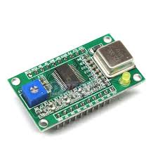
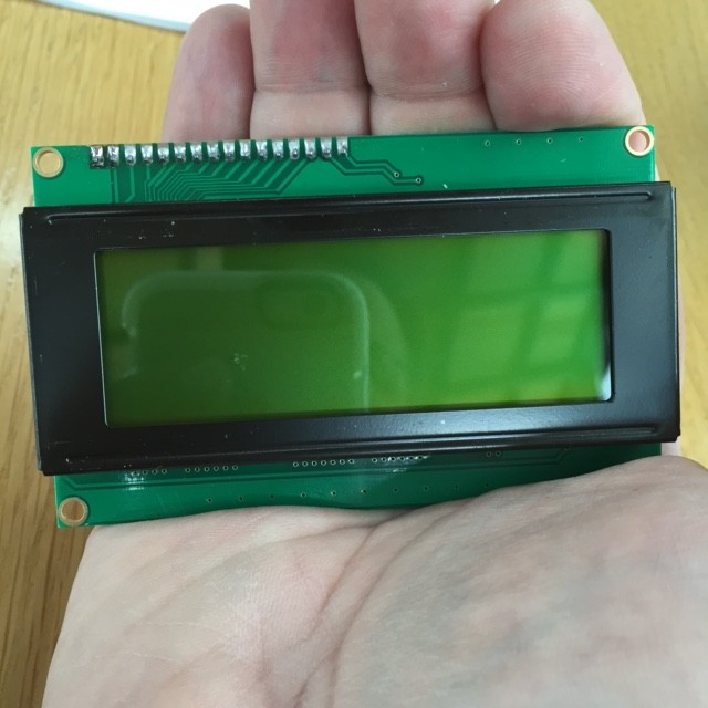
But some code is not part of the standard distribution. For instance, Pete was having difficulty getting an LCD display unit working properly with different versions of the Arduino IDE. I thought it might be a fun excuse to pick up an LCD panel to play with, so I asked him which one he used, and he emailed back this link, which seemed like a cool device. A mouse click, and two days via Amazon Prime, and I had one in my hand.

IMG_0009

IMG_0010

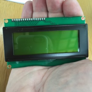
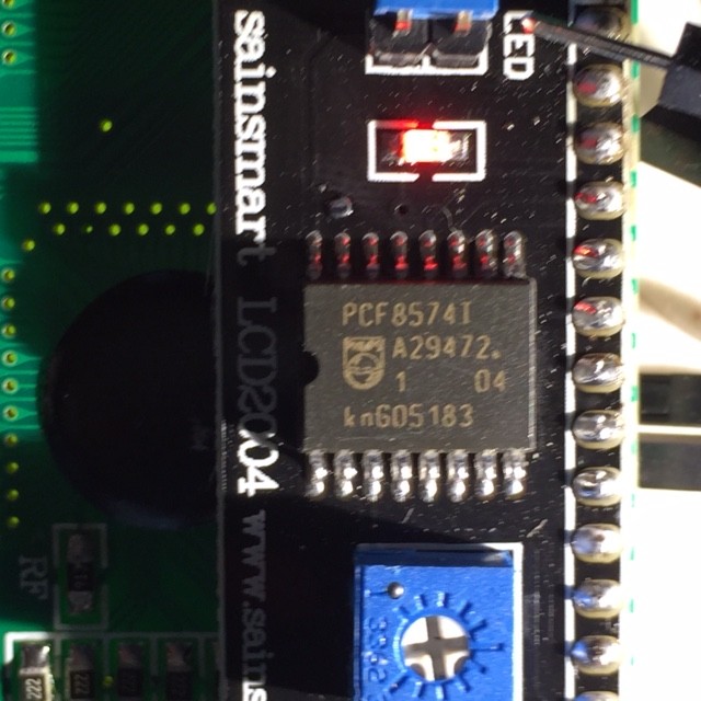
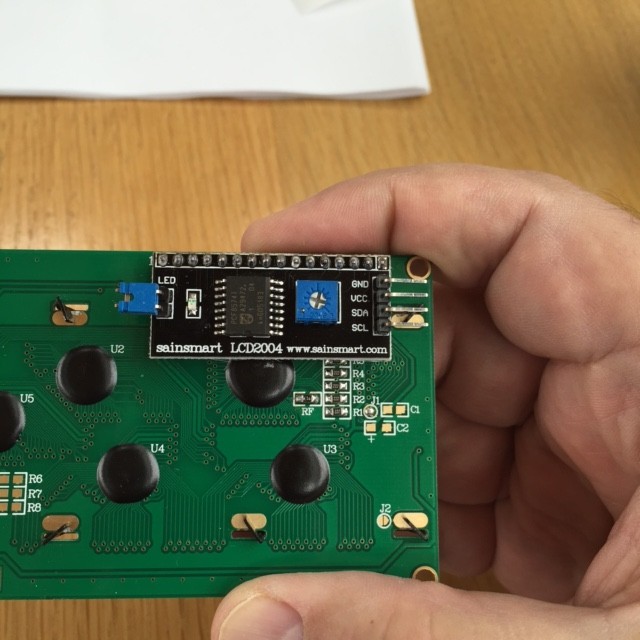
A pretty nice little unit, a little bigger than I expected. If you look at the back, you’ll see that it’s got a little board that looks a bit out of place connected to the back. It’s made by the company Sainsmart, and has four simple pins connected to the back. That board is an converter which turns the display board (which are fairly common, but require a lot more connections) to instead use what is called the “I2C bus”. To get this display working requires a lot less wiring: just +5v and ground, and then two data pins, called SDA and SCL (the “serial data” and “serial clock”, respectively). This makes hardware hookup a lot easier than the conventional (and somewhat cheaper) models.

If you had an ordinary LCD without this backpack, you could use the standard “LiquidCrystal” library that ships with the Arduino IDE (documented here.) If you read the manual page for the “constructor” (the statement which creates a “LiquidCrystal” object that you can interact with), you can see that there are a bunch of ways to create one, depending on how you wire it up. These standard LCD panels require somewhere between six and eleven connections (plus power and ground) which can be a headache.

By contrast, this panel requires only two lines. Awesome! What’s even more awesome is that you can attach other devices that use the I2C bus to the same two lines. Each peripheral has a unique “address”, so programs can talk to each device independently, without adding any more wiring.

But there is a seemingly small problem, one that is familiar to users of desktop computers. To use these special devices, you need a custom library (think of a custom Windows device driver) that knows how to talk to this device. And here begins the problems that Pete and Bill had.

The libraries that ship with the official IDE are usually pretty well thought out, checked to make sure that they work well with the IDE, and are compatible. But this requires a custom library, and those libraries are not always tested against all versions of the IDE. Sometimes they work. Sometimes, not so much.

And, what’s worse is that this code isn’t versioned or vetted. You can have different versions of the code with the same library name. It’s hard to know what versions are the best, which are later revisions and which are earlier, and which were created or modified by, shall we say, less good programmers?

Okay, back to our LCD display.

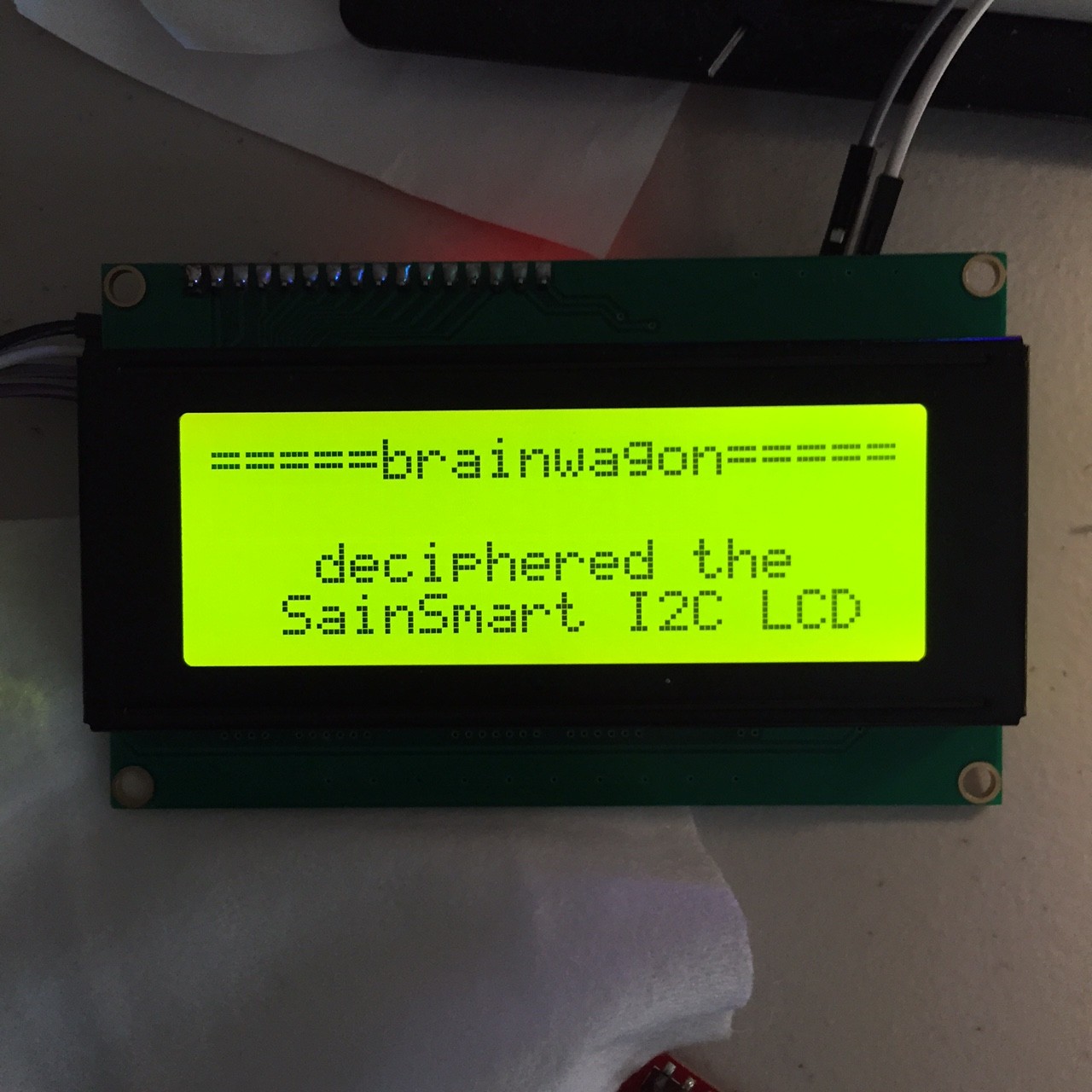
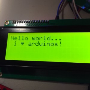
I did what I always do, I googled and found this this version of something called LiquidCrystal_I2C as the top response. That seemed promising. Version 2.0! I downloaded it and installed it (by the way, installing libraries can be annoying in the Arduino IDE, maybe I will rant about that some other day, but you can find out the “right” way to do it here), opened their “Hello World” program, compiled and downloaded and…

Nothing.

Screen glitched a little, and rows of black squares. Argh.

Double checked the wiring. Nothing seemed to be wrong. Hmmm.

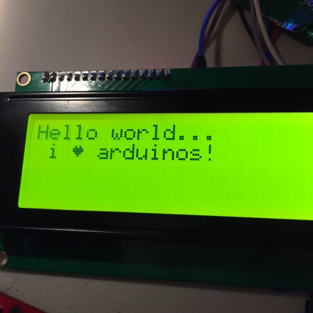
Deleted that version of the library, and after some judicious surfing, uncovered this driver on the dfrobot website. They make a board which looks an awful lot like the sainsmart board. I thought I’d give it a whirl, even though it’s version 1.1 (and therefore presumably older).

Results:

IMG_0011

IMG_0012

It’s at times like this that I feel waves of, well, if not rage then annoyance. I haven’t had the chance to figure out what the issue is (I’m an hour into this already, and it’s supper time) and have no doubt that I’ll be able to figure out what’s going on, but it’s annoying to beginners and experts alike that we have to do this kind of spelunking. Until I sort out this issue, I’ll just make a few recommendations:

  • If you can use hardware supported by the standard libraries that ship with the Arduino, it’s probably worth doing.
  • If you can’t (or choose not to) then perhaps do some searches to find what other people are doing to get stuff working.
  • Document your success and failures as best you can on the web somewhere. Be specific as to which version and platform (Windows, Mac, Linux) you are using.
  • I actually recommend using the latest version of the IDE that’s available at arduino.cc, the official website. The older versions may “work just fine”, but you aren’t going to be able to take advantage of the many bug fixes and updates, and if you are interacting with other newbies, your code may not work. Best to get your own house in order, and then throw stones at whoever has code which doesn’t work properly with the latest official IDE.

To Bill and Pete: I feel your pain. I’d expect a device as common as this to work more or less out of the box. I’ll see if I can make a better suggestion soon. You might try using the code that worked for me, but that’s a poor solution really: I’m recommending using a modern IDE with old code. I’ll work on coming up with a better solution.

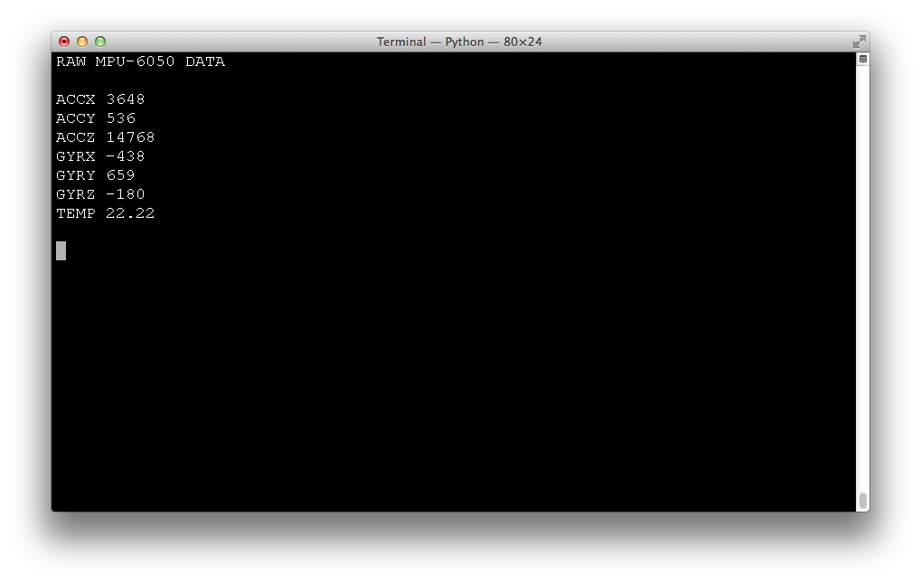
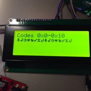
Addendum: Pete, in your email you indicated that the I2C address for your board was 0x3F. On mine, it actually turned out to be 0x27. I found this out by using an “I2C Bus Scanner”, a little sketch that runs on the Arduino and tries to find any devices by running through all 128 addresses. I was shocked to find that it’s not part of the standard examples, but if you google for “arduino i2c bus scanner” you can find code for many simple examples. It should be noted that this one I found screwed me up for a few minutes by printing the address in decimal, rather than hex.

Addendum2: Sigh. I may have been working too hard. Looking at the “official” distribution, it appears that the library does support I2C displays, although as near as I can tell, it’s completely undocumented, and none of the examples will work out of the box. I’ll figure out the right juju to get it to work soon, and will post it below.

Addendum3: In the words of Bill and Pete:


BASTA!!!!!!

Giving up for a moment, it’s acting stupidly on one of my dev machines. Hopefully what I said was not entirely wrong above, but it might be.

Addendum4: I was confused, but the rabbit hole keeps getting deeper. The version installed with 1.6.3 does not support I2C LCD displays. I was misled by looking at my installation on my Mac, which is not the standard 1.6.3, but is based on a system called platformio. When it installs code for the Arduino, it installs this version of the LCD library. You can download the code for it here. It supports both the traditional 8 and 4 bit parallel interfaces, as well as the I2C based version, and seems to be well documented. One bummer: it’s thought of as a direct drop in replacement for the standard system library, so you basically have to delete the installed LiquidCrystal library, and replace it with this one. Read the instructions here. It all looks good, except for one thing:

It doesn’t seem to work properly with the Sainsmart interface either.


BASTA!!!!!!

I know that part of this is that there are dozens of clones and near clones out there, and it’s hard for the library writers to know about all of them, but this is genuinely crazy.

Addendum5: Wow, this is totally crazy. If you go to the Sainsmart page for the “LCD2004”, you’ll find a rar file which includes the library to access this hardware. Except of course, that library is years old and will only work with versions 1.0 of the Arduino IDE.


BASTA!!!!!!

That’s it Bill and Pete. I’m giving up on digital electronics, and am going to spend the rest of the evening looking for good deals on dual gate FETs and crystals for filters.

New I2C peripheral: 6 DOF IMU, $5.89

GYU-52This little gadget arrived via Amazon Prime today: a three axis gyroscope/accelerometer that can be programmed via the I2C bus. I didn’t really have any reason to get one, other than simple curiosity, although I suspect that possibly mounting one on my (as yet unfinished) robot platform might be able to determine motion parameters of the robot.

The board itself is well documented on the Arduino Playground as the MPU-6050 Accelerometer + Gyro. The pinout is rather simple: your normal +5 and GND, SDA and SCL (I2C bus serial data and clock) one address pin (which lets you decide between two addresses for the chip) and an interrupt pin. The chip includes a FIFO buffer, and whenever the chip places data in the FIFO, it triggers the interrupt, indicating that there is data available for reading. Additionally, the chip includes two other lines (XDA AND XCL) which are a separate I2C bus that the chip can use to talk to a magnetometer. Probably won’t be using that anytime soon, but you never know.

IMG_0005As you can see from the picture, it’s really quite small, about the size of a postage stamp, and includes two mounting holes. When I get home, I think I’ll measure up the dimensions and put together the design for a little plastic case that can snap over it and provide some protection for it. The kit includes both right angle and normal headers, I think the right angle will do nicely.

More later.

Addendum: It’s later. Got the thing hooked up. It appears that I needed to ground the AD0 pin to set the address properly (I should double check this, I thought that if I left it floating, it would default to 0x69). Other than that, it’s dead simple. I wrote this code to get raw acceleration and gyro values from the sensor. I’m told that if you divide the raw values by 16384, you get the acceleration in terms of the gravitational acceleration “g”. In other words, if the board was lying perfectly flat on the tabletop, you’d expect that the X and Y accelerations were zero, and the Z would be 16384. Here’s a screen grab:

Screen Shot 2015-04-20 at 8.50.37 PM

As you can see, I wasn’t really quite flat, mostly tilted in X. If you find the lengths of the acceleration vectors, you find it’s something like 0.92 g (we are off by 8% or so). I don’t know what the specs on this thing are, I’ll have to check the datasheet. I know that despite returning 16 bit values, it does not provide 16 bits of accuracy.

Anyway, here’s a simple test sketch:

[sourcecode lang=”cpp”]
//
// A short sketch to read data from the MPU-6050, aka the GY-51
//
// Cribbed from online sources by mvandewettering@gmail.com

#include <Wire.h>

const int MPU = 0x68 ; // I did ground the A0 pin…

int16_t acc_x, acc_y, acc_z ;
int16_t temperature ;
int16_t gyr_x, gyr_y, gyr_z ;

void
setup()
{
Wire.begin() ;
Wire.beginTransmission(MPU) ;
Wire.write(0x6B) ;
Wire.write(0) ;
Wire.endTransmission(true) ;
Serial.begin(9600) ;
}

void
loop()
{
Wire.beginTransmission(MPU) ;
Wire.write(0x3B) ;
Wire.endTransmission(false) ;

Wire.requestFrom(MPU, 14, true) ;

acc_x = (Wire.read() << 8) | Wire.read() ;
acc_y = (Wire.read() << 8) | Wire.read() ;
acc_z = (Wire.read() << 8) | Wire.read() ;

temperature = (Wire.read() << 8) | Wire.read() ;

gyr_x = (Wire.read() << 8) | Wire.read() ;
gyr_y = (Wire.read() << 8) | Wire.read() ;
gyr_z = (Wire.read() << 8) | Wire.read() ;

Serial.print("\e[2J\e[H") ;
Serial.println("RAW MPU-6050 DATA") ;
Serial.println() ;
Serial.print("ACCX ") ; Serial.println(acc_x) ;
Serial.print("ACCY ") ; Serial.println(acc_y) ;
Serial.print("ACCZ ") ; Serial.println(acc_z) ;

Serial.print("GYRX ") ; Serial.println(gyr_x) ;
Serial.print("GYRY ") ; Serial.println(gyr_y) ;
Serial.print("GYRZ ") ; Serial.println(gyr_z) ;

Serial.print("TEMP ") ; Serial.println(temperature / 340. + 36.53) ;

Serial.println() ;

delay(1000) ;
}
[/sourcecode]

Addendum2: Here is a library for accessing the MPU-6050 well (it can return quaternions for orientation, no gimbal lock!).

Tinkering with individually addressable LEDs…

Blinking LEDS...While digging around looking for an LCD module I thought I had stashed somewhere, I encountered a bag with some of 8mm individually addressable RGB LEDs that I had never done anything with. For fun, I thought I’d wire a few of them up on my breadboard and see if I could get them to do something.

These things are cool. Most RGB LEDs have four leads, with one common annode (or cathode) and three other pins, each of which connects to the different color LED. To dim them and generate arbitrary colors, you need to have three pins which are attached to a pulse width modulated pin. To address a bunch of them individually would require a bunch of pins.

But these LEDs are different. It’s true, they have only four pins. But they are constructed to act independently. The four pins are a 5v power pin, a ground, and a data-in and data-out. You can chain arbitrary numbers of them together by hooking the data-out from one LED into the data-in of the next.

To demonstrate this, I thought I’d hook hook three of them together, and see what I could do. It wasn’t obvious to me from the datasheet that I found how the pins were label. Luckily, AdaFruit had a nice diagram that showed how the pins were ordered. I positioned the flat side of each led to the right, hooked all the +5V and ground connections up, and then wired the data-out of each stage to the data-in of the next stage. I then looked up the Arduino, which is dead simple: one output pin to the first LED data-in, and hook up the common ground.

led

To drive this requires a bit of code. The library that everyone seems to use is the Adafruit NeoPixel library. Oh, did I mention? The same LEDs are found in preformed strips like this one. If you need a lot of LEDs in a strip, this is a good way to go. But for just a few LEDs, these through hole parts can be fun.

I downloaded the Adafruit library, and wrote up this chunk of code.

[sourcecode lang=”cpp”]
#include <Adafruit_NeoPixel.h>

const int led_pin = 6 ;

Adafruit_NeoPixel strip(3, led_pin, NEO_RGB + NEO_KHZ800);

void
setup()
{
strip.begin();
}

int cnt = 0 ;

int col[3][3] = {
{255, 0, 0},
{0, 255, 0},
{0, 0, 255}
} ;

void
loop()
{
int i, idx ;
for (i=0; i<3; i++) {
idx = (cnt + i) % 3 ;
strip.setPixelColor(i, strip.Color(col[idx][0], col[idx][1], col[idx][2]));
}
strip.show() ;
cnt++ ;
cnt %= 3 ;
delay(500) ;
}
[/sourcecode]

Nothing too exciting, but it’s been a fun little thing to tinker with. It’s nifty to drive a large number of LEDs using only a single digital pin from a microcontroller. I’ll have to come up with a project to use them sometime.

More camera experiments…

Tonight’s tinkering was inspired by the script by spikedrba that I mentioned in yesterday’s post. I took down the hummingbird camera for a little maintenance, and while it was down decided to do some bench testing with new ideas inspired by what I read.

Sadly, I didn’t have anything as photogenic as hummingbirds to stare at, so instead I just pointed it me in my slightly darkened living room as I hacked on the couch. The video is incredibly boring, but I will post a single frame:

Screen Shot 2015-04-18 at 12.18.25 AM

First of all, I’ve added a text annotation with the time and date to every frame. In my hummingbird camera application, it’s not clear to me that I want it overlaying every frame, but it’s probably useful in a variety of security applications, so I thought it was worth trying. On the line below, you can see three numbers, which represent the load averaged over one, five and ten minutes, followed by two numbers. The first is the number of non zero-length motion vectors that the camera returns, and the second is the sum of the absolute value of differences between adjacent frames. Currently, this application was recording 1280×720 video at 25 fps, and you can see it was using around 36% of the available cpu. Not bad at all. While this version of the script doesn’t actually trigger motion detection recording, it is probably doing virtually all the work that such a script would do, so it’s pretty clear that my stock, non-overclocked model B can easily keep up at this frame rate and resolution.

Spikedrba’s script was very instrumental in figuring out how to setup the pipeline properly to handle this. I also spent some time reading more of the discussion on the picamera github page, and reading the code for the module itself. I’m really very impressed by this.

Once I tighten this up a bit more, I’ll be posting a new revision.

Motion detection in my hummingbird camera…

My goal in experimenting with the Raspberry Pi camera was to try to make an efficient and effective camera which can detect motion. Previous incarnations of the camera script merely looked at the differences in pixel values between adjacent frames, thresholded them at some value, and then counted the number of pixels which exceeded this value. What I discovered was that it was pretty hard to tune the two threshold values in a way that would not pick up changes due to wind motion of the grassy background.

But it turns out that the Raspberry Pi Camera and its associated software picamera has some other tricks up their sleeves. In addition to recording the h264 encoded video, you can record an alternative stream which contains “motion data”, which is essentially some of the raw data that is used by the h264 to do motion coding. Essentially this data provides 4 bytes of data for each 16×16 image block: two signed 8 bit image displacements (in x and y) which represents the estimated image velocity, and a 16 bit value which is the sum of the absolute difference of all the pixels in the block from the previous frame. Both would be rather expensive to compute (certainly in Python) but are quick and easy to extract when computed by the camera itself.

To test my understanding, I modified my camera script to acquire this data, and then transferred it along with the normal video, and then hacked together some scripts using python and gnuplot to superimpose this data atop the background video (which I’ve faded a bit to make the data more legible). The black contours represent the difference data, and are spaced at intervals of 100. The red vectors represent the motion data plotted atop the image.

One thing leaps out at me immediately: the motion data is very good at finding the hummingbirds, even when the birds are relatively stationary. While this clip was not taken in particularly high wind, it’s pretty clear that those vectors aren’t very large in the case of plant motion. Hence, it seems clear I could make a better motion detector by taking advantage of the precomputed motion vectors.

A couple of things remain though: there are obviously drop outs where the contour data drops out entirely. I’m not sure what that is about: it could be a bug in my conversion script, or something more insidious. I’ll go back to the data and find out. Secondly, I’m not sure how capturing this motion data interacts with another feature I use of the picamera: it’s ability to record into circular memory buffers. When I figure out these two issues, I’ll post (and likely github) another version of my watcher script.

Hope this is of interest to someone out there.

Addendum: While doing more reading on the picamera github site, I found a link to this awesome script, which points out a lot of clever things that can be done. I’ll be swiping ideas from it soon!

StarStack… Astrophotography with Cell Phones?

horseheadTom pointed me at this awesome article about an experiment run as part of the BBC programming Stargazing Live. Basically, they asked their viewers to go outside with their cell phones and take a picture of the night sky with their cell phones and upload the (almost entirely black) images to a website. They then used a process called “stacking” that basically aligned all the pixels and added them together. The net result was perhaps better than anyone has anyone had any expectation of getting. Very, very cool.


If you want to see the full image they constructed, click on the version below and you’ll get the resolution they achieved, including some views of the Great Nebula in Orion:

orion

And, as it happens, the kind of thing that I could easily do with the hardware and software that I have lying around. I’m putting this onn my list of experiments to run, maybe with my iPhone, but more likely with the Pi Camera (easier to automate).

Addendum: Glancing at my copy of the Uranometria 2000, my “goto” star atlas, it’s clear that the picture I linked above has all the stars in the Uranometria, which is supposed to go down to about magnitude 9.75. Under dark skies, you’d only see down to magnitude 6 or so. Stars which are magnitude 9.75 are about 32 times dimmer, ordinarily you’d need to use a telescope with a 50mm aperature (a large-ish finder scope) to see these stars.

SSTV from the ISS…

Well, it’s not pretty, but I was just using a 17″ whip antenna on my VX-8GR, recorded it with Audacity, and then decoded it with MultiScan on my Macbook. The first bit of the recording is pretty rocky, so I had to start the sync myself. I’ve bean meaning to do some experiments with bad audio and sync recovery, now I have more data.

Oh, in case this was all gibberish to you, the Russians have been running “events” from the International Space Station to honor their cosmonauts by transmitting pictures via slow scan television (SSTV). I received this picture using what most people would call a walkie talkie, a whip antenna, and a laptop.

As decoded by Multiscan:

iss

I thought a second image would have begun later in the pass, but didn’t hear it.

I think an antenna with a little more gain, and/or a preamplifier would help a lot. You really need pretty noise free audio to make a good picture. Still, a fun experiment. I might try the 12:30AM pass tonight.

Addendum: The second pass was also a little rocky. Got the tail end of one transmission fairly cleanly, but the three minute gap to the next one meant it was low. This is what I got.

second pass