A couple of years ago, I decided to try to get into the entire 3D printing “revolution”. I liked the idea of being able to do some actual design of custom parts, and then be able to render them in plastic. I first bought an Anet A8 kit, and then later a Creality CR-10 which served as more of my workhorse.
But to be honest, the reliability of this printer was never above 80% in terms of my being able to design or download an STL, dice it with Cura, and then print it at reasonable quality without error.
The most common failure mode for prints was simply failure to get the first layer down evenly with sufficient adhesion to keep the print in place until completion. For PLA, the best means seemed to be to use a piece of mirror as the build plate, clean it every time I do a print with isopropyl alchohol, and then carefully preheat the plate, and do a good job of bed leveling.
The stock machine doesn’t include any kind of automatic bed leveling. You simply adjust the z limit switches and the corners of the build plate to try to get it even and calibrated, and then have at it.
That actually isn’t that difficult, but it’s kind of a pain, so I invested in some money to get an EZABL kit. This uses a capacitive proximity sensor to sense the bed position. You can then reflash the firmware of the printer to recognize the printer, and have it autoprobe the bed position before each print.
All that works great. In theory.
But over the last couple of months, I started to encounter a new failure mode that I hadn’t seen before. The proximity probe basically works to act like the previous Z limit switch: when the sensor gets to a certain position, it closes a little transistor circuit to ground the probe pins which used to be connected to a microswitch. When the sensor does this, it opens a red led (there is a similar red led on the sensor itself) to let you know that the switch is closed.
That all seems to work perfectly. But the new failure mode was that the firmware running on the board didn’t seem to see that switch closure, and it would run the stepper into the build plate repeatedly. The Z axis drive belt would then slip making an annoying sound which would continue forever, or at least longer than I could stand before switching the printer off and resetting.
Irritating.
It did it a few times, then mysteriously it stopped. I was making prints related to my telescope refurb project, and then suddenly it was back. Annoying. I did some brief testing. The sensor was detecting the position just fine, but it didn’t seem to register as a triggered event.
I finally got fed up, and sat back and thought. “If the cable connecting the sensor to the Z limit switch had a fault, that would be bad. How can I test it?”
Well, you need to disassemble the printer, pull the cable and verify its operation. So I disconnected the printer from its position in the corner of my dining room, carefully cleared my garage workbench so I would have plenty of work, and moved it there for disassembly.
It’s kind of annoying to disassemble the control box. The motherboard is mounted on the underside of the metal control box, with a 12V generic power supply module in the way. I had done it before, but I had forgotten how annoying it was. I eventually got all the parts pulled out, and extracted the cable in question. I set my multimeter into continuity check mode and…
The cable seems fine. Frown. Maybe it was just loose? I could take the half hour or so to reassemble it (annoying, since it feels like the kind of job that could just take a few minutes) but there would be no guarantee that I wouldn’t immediately have to take it apart again. Should I just spend $12 or so and order a new cable pack just to be sure?
While I had the motherboard out, I decided I should at least take the time to reflash the firmware (there were a couple of changes that I was thinking of making anyway). The motherboard is based upon the same sort of Arduino chipset that everything seems to use, but for some reason (ROM space?) it doesn’t include a boot loader, so needs to be reflashed via a six pin port. It would be easier to do this while the printer was apart.
But then I noticed something bad. The mini USB socket mounted on the board was loose. While examining it… it simply tore loose.
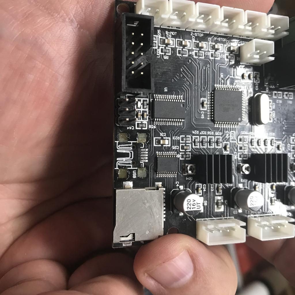
So… I could probably fix this. I could get a new socket, mount it in place with a little CA glue, find a smaller tip for my Hakko soldering station, and replace it. And in fact, I just went ahead and ordered some cheap USB connectors to do that.
But I wonder whether I shouldn’t just chuck this old 8 bit motherboard in the bin and move to something more advanced.
So I took what was a very small and limited project, and expanded it into something that will probably take me a couple of weeks to complete. I ordered a BIGTREETECH SKR 1.4 motherboard. https://www.amazon.com/gp/product/B082YTZJS2/ref=ppx_yo_dt_b_asin_title_o02_s00?ie=UTF8&psc=1 This has a number of interesting added features compared to the previous motherboard. It is based around a 120Mhz 32 ARM processor instead of the 20Mhz 8 bit Atmel chip that runs the old motherboard. It uses the stepper motor modules that are common, rather than having the steppers built into the original model. It can support multiple extruders and dual Z axis motors (nice expansions). It can also talk to the new stepper modules via serial connections, enabling you to set motor currents via software rather than tuning them with screwdrivers. And it also supports limit detection without limit switches: it detects the rise in current as the motor hits the end of motion, and uses that to trigger the limit events.
Oh, and I can compile the firmware and install it just by putting it on an flash card and rebooting the machine. Nice.
But it this does represent a significant set of new challenges as well:
- It’s complicated. Lots of new stuff to learn. New software options to reconfigure. New technologies (like no limit switch and serial motor drivers).
- It’s not actually mechanically compatible with my existing setup. If I were to try to put it back in the same box, the USB and microsd slots wouldn’t line up. That means I’m committing to building a custom case for it.
- It doesn’t actually address the sensor issue that originally started me on this journey in the first place.
But that’s the path I’m on. I think that I’m going to get some 1/4″ Baltic Birch ply and use some of my box building skills that I’ve been practicing and make a simple enclosure to hold the parts, but with plenty of room to make them all easily accessible. I think I’ll also include space for the Raspberry Pi 4 that I use to run Octoprint. I may make this the same size as the base of the printer, so I can actually stack the printer on top and reduce the overall footprint.
I’m trying to look at this as another skill building exercise, which is rather the point of my projects anyway.
If anybody has embarked upon a similar path, drop me a note (twitter is a good place @brainwagon) and let me know if you want to talk me through (or out of?) this line of endeavor.
Hope you all are well.