Category Archives: Raspberry Pi

RTL-SDR on Raspberry Pi…

Just a quick note. I have been meaning to try out the combination of the Raspberry Pi with one of the popular $20 RTL-SDR dongles, to see if the combination would work. I was wondering how well it would work, how hard it would be, how much of the available (small) CPU power it would use. The short answers: reasonably well, pretty easy, and maybe 20% for rtl_fm. That’s pretty encouraging. I’ll be experimenting with it some more, but here’s a short bit of me recording KQED, the bay area PBS FM station, using the pitiful tiny antenna that came with the dongle. It should be noted that my house is in a bit of a valley, and FM reception in general is quite poor, and I recorded this from inside my house, which is stucco and therefore is covered in a metal mesh that doesn’t help. Not too bad. I’ll work out a better antenna for it, and then try it more seriously.

Addendum: Here is a page with lots of good information on RTL-SDR/dump1090 on the Raspberry Pi.

Some continuing short bits on SSTV….

Nothing too exciting going on, but minor bits of code and play have been done, so I thought I’d update.

First of all, there is a program for decoding SSTV on the Pi, called QSSTV. I don’t have a proper sound setup on the Pi yet, so I couldn’t test it live on the air, but I did take one of my pregenerated Martin 1 images and asked it to decode, which it did quite well:

shot

Not bad at all. While investigating qsstv’s capabilities, I discovered that the latest 8.x versions suppert digital SSTV. Well, except it isn’t built into the qsstv version (my guess is that the Pi doesn’t have quite enough oomph to do the necessary math in real time). But that’s pretty cool: I’ll have to check that out sometime soon.

But anyway…

I also coded up a Scotty 1 encoder, so now I have encoders for Martin 1, Scotty 1, Robot36 and Robot72 modes. I found this great book online which had many details about the different modes. It was quite helpful. It actually documents the modes a lot better than the ARRL Image Communications Handbook and is, well, free. Awesome.

One question I’ve been interested in for a while is “which mode is best?” Of course, we have to define what we mean by “best”. After all, Robot36 sends an image in half the time of Robot72, and about one quarter the time as Martin M1. My question was: how much better image can we expect from Martin, given that it takes 4x as long. Another question was “how much bandwidth does each mode use?” In the ARRL Image Communications Handbook, they have a formula which computes bandwidth but it didn’t make a great deal of sense to me.

I don’t know how to precisely answer either of these, but I thought I’d write some code to simply compute the power spectra of a bunch of some sample sstv recordings. So I did. It basically just loads the sound samples from the SSTV file, window it (I used the Blackman-Nutall window, for no real reason) runs an FFT (using the fftw3 library) and compute the power spectrum. It’s pretty easy. I then encoded a simple color bar image in three different modes, and graphed them all up using gnuplot.

spec

Staring at it, well, they don’t seem that different really. I should figure out the frequency bounds that (say) cover 85% of the total energy, but just eyeballing it, it doesn’t seem that bad.

I also did some minor tweaking to add in additive white Gaussian noise, but I haven’t gotten that entirely working so I could do an apple to apples comparison of how each modes does in total power at various levels of noise. And I’m looking for an HF path simulator too.

That’s about it for now. Stay tuned for more.

Additional Experiments with SSTV, with some ideas….

Previously, I had written an encoder for the Robot 36 SSTV mode. I chose this for a simple reason: it appears to be the most common mode used in downlinks from satellites, such as the ARISSat-1. It’s not a bad choice, and presents reasonable quality in just 36 seconds.

Today, I decided that I should probably go ahead and implement another of the “Robot” modes, specifically Robot 72. It transmits images with the same resolution (320×240) as Robot 36, but with a bit better quality, and I suspect a bit better fidelity. Both modes transform the RGB colors of the original into a different color space with a luminance channel (usually labeled Y for Ylluminance) and the color encoded in a R-Y and a B-Y channel. To speed transmission, Robot 36 downsamples the last two channels into half resolution images in both dimensions (it really only sends a 160×120 image in those channels). Robot 72 does a similar thing, but only downsamples in the horizontal direction, sending R-Y and B-Y in 160×240.

It wasn’t too hard to modify my Robot 36 code to transmit Robot 72. For fun, I set it up and tested it. It works! Sending the resulting file to my Macbook and decoding with Multiscan 3B, I got:

wall

(The image has been expanded by 2, to 640×480, which makes it look a bit soft)

So, anyway, I was thinking about where to take this idea a bit further. I want to create a project that others can duplicate and expand upon, and that maybe promote the SSTV in a way that is amusing and fun. I wanted to build upon the work I’ve done so far, but take it further, and make it into a project that others might want to duplicate.

What I envision is a small box, consisting of a Raspberry Pi, a Raspberry Pi Camera, and a PiTFT display, together with a USB sound card like this one. (You need a USB sound card because while the Pi does have sound output, it doesn’t have sound input.) Add a microphone and a speaker. This collection will be interfaced with a radio: let’s assume for the moment an amateur radio like a the little Baofeng BF-888S radio I’ve been playing with. Add some buttons for interface.

Here’s what I’m imagining as the use case: it’s an interface to your HT. You could talk, and have it relayed to the radio. You could listen to the radio through the speaker. But you can also click a different button, and it will capture and send an image via SSTV. And if it hears an SSTV image, it will decode it and display it on the TFT display. I’ll probably initially support some of the low resolution black and white modes as well as the Robot 36 and Robot72 modes. I can also imagine a keyboard interface that will allow you to add text to your live images and send it out as well. The fastest, lowest resolution BW modes are just 160×120, and transmit in just 8 seconds. With an 8×8 character matrix, you can send the equivalent of a tweet (about 120 characters) in one image.

To make this work, I’ll have to work on a demodulator. So that’s the next step. Stay tuned.

SSTV travels through the Ether! A minor success!

So, this morning I played around a bit more with my Raspberry Pi code to try to see if I could make an SSTV beacon. The idea was to use two existing bits of code, raspistill and my own SSTV encoder (robot36), and glue them together with a small bit of Python. The code uses raspistill to snap a 320×240 image, a bit of the Python Imaging Library to add some text, then my own robot36 encoder to convert that to a sound file. The Pi would then play the sound file, which would be piped into my $17 BF-888S transmitter, which was set into VOX mode, which means that when it hears a signal, it begins to transmit. For this test, I used it in the low power setting, transmitting on the 70cm calling frequency.

To receive, I fired up my trusty FT-817, which was then piped into my Windows laptop running the classic MMSSTV software. At first, I tried using the laptop mic to just listen to the sound played on the 817, but the results were less than stellar. I finally found the right cable to do a direct connect, set the levels appropriately, and voila (I doubled the image size for easier viewing):

cqk6hx

Not bad! Total distance: maybe 35 feet or so (blocked by two walls). After I was done, I realized that I actually don’t have an antenna hooked to my FT-817, so I suspect much greater ranges are capable. The BF-888S is basically operating as an FRS radio here (in fact, the BF-888S can be programmed to act operate on FRS frequencies) so even if you don’t have an amateur radio license, you could probably build a similar setup without a lot of hassle.

Fun.

Some thoughts on SSTV and the Raspberry Pi…

Screen Shot 2014-03-06 at 9.55.29 PMToday I found an interesting Instructable on running SSTV on the Raspberry Pi. It uses an interesting bit of software which uses the Pi to directly generate an FM signal. Strictly speaking, I doubt this is a great idea without some outboard harmonic filtering, but it’s cool that it could be done.

I recalled that a while ago I wrote an encoder for the Robot36 SSTV mode. I wondered how efficient it was: could it be used to construct a nice Raspberry Pi SSTV beacon? I transferred it over, installed the necessary dependencies (the jpeg library and libsndfile1) and timed it. Eek. 18 seconds to encode image. That seemed excessive, so I set about figuring out why it was slow.

It didn’t take me to long to discover that the vast majority of time was spent in the libsndfile library. That was in no small part because I used it to write individual floating point samples, one at a time. I hypothesized that if I buffered up a bunch of samples, it would be better. So, I coded it up quickly, and voila: it now can decode a jpeg and create the resulting wav file in just 1.878 seconds. Awesome. Playing the wav file back into Multiscan (an OS-X SSTV program) resulted in just the image I wanted.

It should be pretty easy to modify this script to read directly from the Raspberry Pi camera and send it directly to the sound card. A little bit of interfacing to an HT, and I should have an SSTV beacon ready to go. Stay tuned.

Raspberry Pi Camera NoIR…

I’ve been playing around with the Raspberry Pi Camera for a number of different purposes, but one thing is pretty apparent right off: while the quality overall is quite good, it’s not very good in low light. Because at least part of my potential application is watching the night-time activities of wildlife (most likely my cat, but perhaps including foxes that cruse around yard) I decided to order the version of the Raspberry Pi Camera which had no IR blocking filter, called the Raspberry Pi NoIR. It arrived today, and at the same time I ordered an inexpensive IR illuminator to serve as a light source. Addendum: The illuminator died after less than 12 hours of use. Do not buy this one. It’s rubbish.

It arrived today!

Out with the old camera, in with the new, power on the illuminator (if you order the same one, note that it does not come with a wall-wart to power it) and voila:

Screen Shot 2014-02-10 at 8.35.00 PM

Scrappy Cam!

Okay, a couple of quick notes. The illuminator is just not that strong. Here, the illuminator was a little under five feet from the the couch. For stuff that is more distant, it’s clear that the illuminator just isn’t good enough to reach into the corners of the room. Check out…

Screen Shot 2014-02-10 at 8.33.32 PM

You can see me standing to the side. Obviously, the color balance is all wonky, it’s going from magenta to purple. The frame rate is still quite low, which in my streaming application manifests itself as a pretty long delay. Still, seems pretty cool! More experiments soon…

Streaming Video From the Raspberry Pi Camera…

First of all, let me get this off my chest: video over the web is a hideous Tower of Babel.

With that basic complaint, let me start by saying that this project started with a Raspberry Pi and the Raspberry Pi Camera. Previously, I had used the Pi with a USB webcam and had connected it to my wireless router and run the “motion” program to serve as a kind of cat cam. But to be honest, I wasn’t really very happy with the results. The videos it recorded were low frame rate. The quality of the camera was pretty low. It was good enough to allow me to monitor my cat while I was on vacation, and have some assurance that he was still alive, but it left something to be desired.

After picking up some new $8.88 TP-Link Wifi dongles, I decided to see what else I could do. The trick with making this work was trying to find a way to leverage the video compression hardware that already runs on the raspberry pi, and to do as little as possible to it, but still allow it to be streamed to standard web browsers and devices.

I briefly went through experimenting with mjpegstreamer which works, but didn’t really offer the quality that I was after.

Then, I stumbled on this great article on using nginx-rtmp to stream live video from the Raspberry Pi. It looked like just what I wanted. It took me an evening (mostly spent waiting for nginx and ffmpeg to recompile) but I have it working now. Check it out:

Screen Shot 2014-02-06 at 8.56.16 AM

I’m currently able to stream 720×486 wide video at 25fps directly from the Pi at around 25fps, using somewhere around 13% of the available cpu on the Pi. It can be accessed by both desktop browsers and my iPad/iPhone. Seems really good!

With a couple of caveats. Remember that Tower of Babel I mentioned? Yeah, that. To stream to desktop browsers, they must run Flash. That is because nginx-rtmp uses RTMP, which is a proprietary streaming video protocol. But, I’m sure you say “how does this work on the iPad/iPhone?” The answer is it uses a different protocol for those devices, the HTTP Live Streaming protocol, which is also transparently supported by the RTMP server. Why can’t you just use HLS on the desktop? Because most desktop browsers don’t support HLS. Sigh. HLS also has increased latency compared to the RTMP protocol.

Sigh.

But anyway, it works! I’m awaiting the arrival of an Raspberry Pi camera with the IR filter removed and an IR illuminator, and I’ll be doing more experiments. I’ll maybe write up more explicit instructions for this when i get the entire thing working. If anyone wants to give this a try and has trouble, don’t hesitate to sing out with questions.

An $8.88 WiFi adapter for my Raspberry Pi…

g1I was out running errands the other day, and found myself at Fry’s Electronics. I needed to pick up a VGA extension cable to replace one that had inexplicably become bad, and as I often do while wandering around, found myself doing a bit of window shopping. (Not Windows shopping, I’ve had enough of that.)

While doing so, I found myself staring at a variety of wireless network dongles, including the exceptionally tiny TP-Link WN725N for a mere $8.88. I wondered if it might be a good match to a couple of the network-less Raspberry Pis that I had lying around. A little of judicious searching on my phone indicated that some people had used them for this purpose, and that they worked well even without a hub, so I bought two of them and brought them home.

I was hopeful that if I just jammed them in, they would be detected automatically and then a short bit of network config later, I’d have a working adapter. Sadly, it did not go that smoothly. It appears that while v1 of the hardware worked out of the box with Raspbian, the v2 hardware (which I had) does not. So, the google search begins…

Ill skip to the end, so you won’t have to do the search. Go to this website, it has all the information. Basically, you have to find the right version of the kernel model to match your version, and install it in the right place, and rerun depmod -a. They even have a link to a script that can find the right version to download. Once I got the driver installed, I had no further issues. The dongle appears to work quite well, and my raspberry pi no longer has a tail connecting it to my router. Awesome! I haven’t stress tested it, but it appears to work as well as any other adapter I’ve tried. I consider the experiment a success.

Arduino Bumper Shell, created with OpenSCAD

brackets
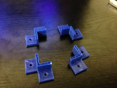
Last week, I got a chance to experiment with a Replicator 2, and printed some brackets for my robot project. I designed them using OpenSCAD, which is kind of a scripting language for solid shapes. It can export in STL format, which I then used MakerWare to drive the Replicator 2. The picture at the right shows my first attempt, which aborted when my silly laptop went to sleep. Still, the brackets worked out pretty well. The holes in the bracket were coded to be 0.125″ in diameter, which is a loose clearance hole for #4 hardware. The resulting brackets actually were close to tap size: I could thread a screw into them, but not push one through it. That seemed like a pretty good test.


bumper
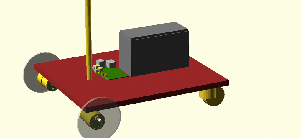
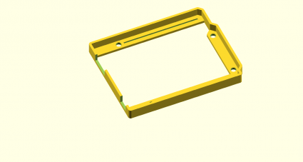
While digging around for new stuff to make, I saw a “bumper” style case for the Arduino on Thingiverse. I thought that might an interesting project, and I needed something like this to mount my Arduino onto the robot platform I’ve been working on. In about an hour, I coded up one:

[sourcecode lang=”cpp”]

module arduino_outline() {
polygon([[0, 0],
[0, 2100],
[2540, 2100],
[2600, 2040],
[2600, 1590],
[2700, 1490],
[2700, 200],
[2600, 100],
[2600, 0]]) ;
}

module edge () {
difference() {
minkowski() {
arduino_outline() ;
circle(62.5) ;
}
minkowski() {
arduino_outline() ;
circle(8) ;
}
}
}

module bands() {
minkowski() {
square([2600, 200]) ;
circle(10) ;
}
minkowski() {
translate([0, 1900]) square([2600, 200]) ;
circle(10) ;
}
minkowski() {
polygon([[2600, 1590],
[2700, 1490],
[2700, 200],
[2600, 100],
[2500, 200],
[2500, 1490]]) ;
circle(10) ;
}
}

d = 31.25 ;
w = 16 ;

module bumper() {
difference() {
union() {
linear_extrude(height=250) edge() ;
linear_extrude(height=62.5) bands() ;
}
union() {
translate([550, 100]) cylinder(r=125/2., h=500, center=true) ;
translate([600, 2000]) cylinder(r=125/2., h=500, center=true) ;
translate([2600, 300]) cylinder(r=125/2., h=500, center=true) ;
translate([2600, 1400]) cylinder(r=125/2., h=500, center=true) ;
}
translate([-75, 125, 63]) cube([525, 300, 500]) ;
translate([-250, 1275, 63]) cube([625, 500, 500]) ;
translate([1100, 100, 62.5]) translate([-w, -w, -d]) cube([1400+2*w, 2*w, 2*d]) ;
translate([740, 2000, 62.5]) translate([-w, -w, -d]) cube([1740+2*w, 2*w, 2*d]) ;

}
}

scale([25.4/1000., 25.4/1000., 25.4/1000.]) bumper() ;
[/sourcecode]

I haven’t had the chance to print it yet, so it might not be exactly right for fit, but I’ll let you know how it works out.

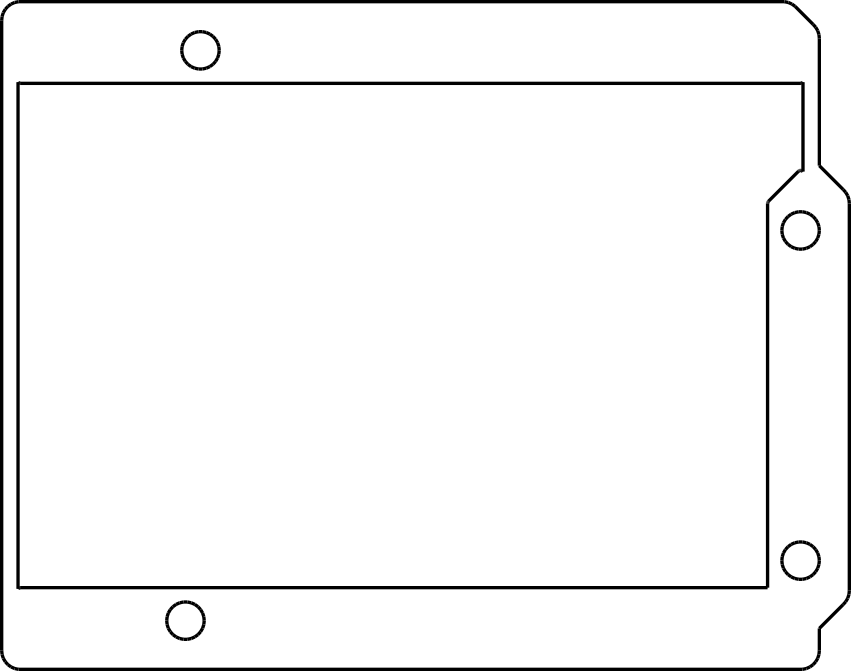
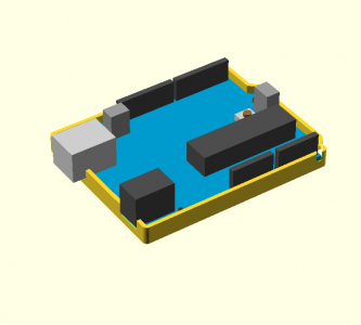
Addendum: I found a model for an Arduino in OpenSCAD, and tried merging it with my bumper. That revealed that I had made a mistake in the code listed above: the DC connector should be 350 mils wide: the slot as coded would be too narrow. I also decided to widen the relief channels for the pins which stick out the bottom, and provide an extra depth relief to support the DC and USB jacks. When I get a chance to print this out, I’ll probably upload the kit-n-kaboodle to thingiverse once I’m happy with it.

Until then, here’s the tease:

witharduino

Addendum2: I experimented a bit with export options. I projected the bumper down to 2D, exported it as DXF, and then imported it into Inkscape, where I could convert it to a 300dpi bitmap. Voila.

path3391

Using the Raspberry Pi as a wireless webcam server…

webcamThe other day, I was walking around in Fry’s Electronics, and noticed that they had HP HD-2200 webcams on sale for a mere $6. I thought to myself: hey, even if the camera is crappy (and it is) that is simply too cheap to pass up, and grabbed one. Last night, I decided to try to pair it with my Raspberry Pi and the WiPi dongle, and see if I could make a simple webcam that I could move around. Over the next 30 minutes or so, this is what I came up with.

The driver for the webcam already existed. The USB driver lists the maximum power from this webcam at 200ma, which seemed modest enough, so I configured my Raspberry Pi with the WiPi and webcam plugged in directly, without any powered hub. Technically, the combination of the WiPi and the Pi might be over the reasonable limit, but I have seen others do a similar setup, so I decided to step boldly. This is nice, because it means that you just have one plug, and the resulting package is quite compact and mobile.

Experimentation using ffmpeg to read from the v4l2 device showed that the camera needed to capture a few frames before the automatic exposure would yield a decent image, so I grumbled a bit and experimented. After 10 minutes of inconsistent results, I recalled hearing about a different but simple webcam server program called fswebcam. It’s a simple little program, and was in the package repository, so a simple “sudo apt-get install fswebcam” and I had the software installed. It’s got a pretty good man page too. Fswebcam doesn’t stream video, but it can do one-shot and periodic captures, and has a lot of the essential features that I wanted, including capturing and skipping a bunch of frames, and capturing and averaging a bunch of frames for output.

This morning, I left my camera aimed at the bed in our guest room, which is where my cat Scrappy likes to take his naps. I hoped that later in the day, I’d be able to get a picture of him. The room has some direct sun during the day, which makes for some harsh lighting, which makes the picture pretty unimpressive.

output

Nope, he wasn’t napping there. Or was he? I loaded the image into gimp, and stretched the contrast with the Levels adjustment:

scrappy

Ahah! Hiding next to the wall! (That’s a cloud painted on the wall above and to the right of him).

Pretty neat.

Oh, incidently, I didn’t have an http server installed on the Pi, but then remembered that it does have python. If you run “python -m SimpleHTTPServer” it will create a webserver that can serve files out of the current directory on port 8000.

Later, I may try to use ffserver or motion to do something fancier, but I’m happy with this setup so far.

The Raspberry Pi, and the WiPi USB dongle, with questions about power…

I’m having lots of fun with my Raspberry Pi, and I’ve decided to launch one of my crazy spare-time projects: inspired by this article detailing the construction of RUDEBOT, a kind of mobile tablet robot, I decided to build a robot of my own. But, anything worth doing is worth changing and adapting, so I thought I’d put my own spin on it, and use the Raspberry Pi and an Arduino combined to provide the brains of this robot.

wipi The original incarnation of the RUDEBOT used an Arduino and a WiFi shield. I didn’t like this approach because the WiFi shield is, by all accounts, fairly buggy and limited, and the actual cost of the shield is rather high. It dawned on me that I could buy a Raspberry Pi and a WiPi (the tiny USB 802.11n dongle you see on the right) for less money, and I’d have the advantage of also carrying a full Linux computer on board. I could turn my incarnation into a kind of mobile hotspot, which seemed like it might be a fun thing to try. I would still use the Arduino to handle the basic motor controls with commands sent over a serial port from the Raspberry Pi. Having that much hardware on board makes all sorts of software possible.

robotWhile waiting for parts to arrive, I just sort of began doodling using OpenSCAD to design the basic layout. I built CAD models for the motors and the platform, and selected a 12V 7 amp hour SLA battery. And then… began to think about power.

The documentation says that the Raspberry Pi can consume up to 700ma of current while running. Often, you’ll see that whenever anyone adds any significant USB peripherals to a Pi, they use a powered USB hub. In theory USB devices are supposed to be able to request 500ma of current from the host, but the Raspberry Pi (the second version, the originals ones had even lower power capabilities) has fuses which limit total current at 1A. So clearly, power hungry peripherals can require additional power, and a powered hub is the common solution.

But which peripherals are power hungry? In particular, it would be great if I could hook up the WiPi wireless dongle without having to provide additional power. So, I set out to research whether it was feasible. I saw three ways to proceed:

  1. Simply try it. If it works, then it works. Hard to argue with that, but it doesn’t tell you a lot about what the limits are. Would adding an additional keyboard/bluetooth/mouse push it over the edge? Undisciplined trial and error doesn’t seem like a good approach.
  2. Try it, but measure the current required. This seems like a better approach, and gives you hard data. Basically I’d need to tap a microusb cable so that I could put in my trusty multimeter, and I could measure the current directly. I probably will do that soon.
  3. Try to research how much current these things are spec’ed to use.

The last is easy to do when you have an iPad in front of you during lunch, so that’s of course what I did. But the figure that I’m interested in (power consumption) is not very often listed for USB peripherals. But it turns out that USB peripherals are supposed to give some hints to the host about how much power they require. If you plug in a peripheral to your Linux box (including the pi), you can simply use the command “lsusb -v” to get a dump of all the USB devices, and see what the driver for the hardware thinks it needs.

So, I did just that. I plugged my WiPi into the powered hub, and had a peek. Here’s the dump, most of which is pretty uninteresting, but which contains the Max Power…

Bus 001 Device 008: ID 148f:5370 Ralink Technology, Corp. RT5370 Wireless Adapter
Device Descriptor:
  bLength                18
  bDescriptorType         1
  bcdUSB               2.00
  bDeviceClass            0 (Defined at Interface level)
  bDeviceSubClass         0
  bDeviceProtocol         0
  bMaxPacketSize0        64
  idVendor           0x148f Ralink Technology, Corp.
  idProduct          0x5370 RT5370 Wireless Adapter
  bcdDevice            1.01
  iManufacturer           1 Ralink
  iProduct                2 802.11 n WLAN
  iSerial                 3 1.0
  bNumConfigurations      1
  Configuration Descriptor:
    bLength                 9
    bDescriptorType         2
    wTotalLength           67
    bNumInterfaces          1
    bConfigurationValue     1
    iConfiguration          0
    bmAttributes         0x80
      (Bus Powered)
    MaxPower              450mA

450ma. Ouch. That seems like a lot. I find it kind of hard to believe that such a tiny transmitter can pull that much current without melting itself (it’s tiny). So, I’m left with some questions:

  1. Can the WiPi really pull that much current?
  2. Can I use it without plugging it into a powered hub? Some people do seem to be doing that, and have even said that it doesn’t work properly when plugged into some powered hubs.
  3. I’m also interested in hooking an Arduino to the Pi. How much current can the Arduino pull?
  4. Ultimately, I probably will want to power all of this equipment with my 12V SLA battery. What’s a reasonable solution to powering the Pi, Arudino and potentially a powered hub? I’m looking for quick and dirty, but also reasonable and reliable.

Any hints from robot/power/Raspberry Pi experts are welcome, here or via twitter @brainwagon.

A new little computer: the Raspberry Pi…

Sorry it’s been a while since I wrote anything here. The simple fact is that I haven’t done a lot that’s very interesting lately. But Carmen did buy me a Raspberry Pi for Christmas, and I’ve been playing with it a bit. As it happens, we had a power outage over on the 26th, and when my rapidly aging FreeBSD server (a 1Ghz Via C3 Nehamiah processor, released in 2003, if memory served) rebooted, one of its drives seems to have failed. I mostly use this machine for an ssh and IRC server, some local web and file serving, and the odd bit of Python and C programming. I have been considering replacing this 10 year old machine, but until I get around to putting something reasonable in it’s place, I thought I’d see if the Raspberry Pi could serve.

And the answer is yes, it can.

I installed the Raspbian distribution of Debian, and plugged it into my router. Enabled ssh, and voila! Works great. Well, it’s pretty slow. I have a class 4 4GB card serving as its only storage, which is not exactly brilliant, and the 700Mhz clock rate is pretty… well… slow, even by comparison to the 1Ghz machine it’s replacing. But it does work! It’s even got an X server, which isn’t exactly zippy, but which does work.

For fun, I thought I’d give it a bit more of a test. I installed simh, and then transferred my TOPS-10 disk images over. The Raspberry Pi actually makes a pretty nice little PDP-10 simulator. I’ll have to benchmark it later, but it seems to work just fine.

I’ll have more details later, but for $35, it’s a lot of computer. Barely more than an Arduino Uno, but with a lot more capability.

Highly recommended.