Category Archives: Teensy

More on my 8 digit clock, now with GPS synchronization…

Yesterday I just had a few minutes to hack around, and I decided to marry a sketch that used the TinyGPS++ library to the clock display that I had working the other day. I’ve been hopping back and forth between the Arduino and the Teensy LC as a development platform. Since I still had the display hooked up to an Arduino (actually the Sparkfun RedBoard, my favorite compatible) I decided to hook up the GPS to the RedBoard as well, to serve as the time source: the Arduino would wait until the GPS acquired a lock, and would then begin displaying the time.

Because the Arduino Uno (and RedBoard) have only a single dedicated serial port, the usual way to connect a GPS is to create a SoftwareSerial port using (say) pins 5 and 6. So, that’s what I did initially. It worked, but I found that whenever you did a Serial.read(), it caused a minor glitch in the timing of the refresh. At the beginning of each second, when the GPS squirts a substantial amount of text to be received, the entire clock display noticeably flickers since the Serial.read() messes with the timing of interrupts (presumably, by blocking them for a short but significant period of time). Bleh.

In the end, I ended up hooking the GPS pins to the hardware serial port on pins 0 and 1. The problem is of course that then the pins are unavailable for other uses, such as printing status back to your USB port, or (notably) downloading new code. I had to disconnect the GPS, flash the software, and then hook up the GPS again. The result was nice and smooth, no flicker.


A much better solution is to use a small board like the Teensy LC or Teensy 3.1. They each have three dedicated hardware serial ports in addition to the normal Serial device which can communicate back through the USB port. The Teensy 3.1 even includes hardware FIFO buffers, which will enable even more flexibility.

When I get some free time, I’ll probably include intermittent display of both latitude and longitude. Because I can, that’s why.
How much time is spent refreshing my 8 digit LED display?

A couple of days ago, I wrote about experimenting with a little Chinese 8 digit, 7 segment LED module that is driven by some 74HC595 shift registers. My initial experiment in driving it with the Teensy was successful: I got a nice, steady display with a simple interrupt driven scheme which displays each digit for two milliseconds before moving on to the next. But I wondered what percentage of my total time was actually being spent refreshing this display. In particular, how fast was the interrupt routine?

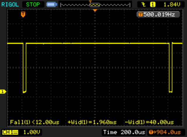
Most of the time spent in the interrupt routine is presumably spent in serially clocking out the individual bits to the shift register, using the Arduino library function shiftOut. I thought about adding some timers and computing what the time left, but this morning, I realized that I could use my nifty Rigol scope to figure out how long it took, by looking at the LATCH signal. Before clocking the data, the LATCH signal is brought low, and then afterwards brought high again. There are a couple of instructions on either side, but it’s not a bad approximation.

When I got home, I hooked up the scope.

NewFile2

Nifty! The total time accounts for 40 microseconds out of every 2000 microseconds, or about 2% of the total runtime for the Teensy. Nice! Works great. My guess is that it would be significantly more as a percentage with a traditional Uno. Perhaps I’ll try that out soon.

Addendum: I installed the same code on the Sparkfun Redboard (an Arduino Uno clone, which is an ATMEGA328 running at 16Mhz). With identical code, I used the same setup. The interrupt routine runs in about 360us, about 9x slower, consuming about 18% of the available CPU cycles. If you double the period to 4ms, you could halve this, but I find that the strobing of the ~33hz display to be slightly too much for me.

Driving an 8 digit, 7 segment display based upon the 74HC595…

A few weeks ago, I was scanning the Deal Extreme website, and ordered a few different LED displays, not because of any pressing need, but because I wanted to have some display options available if I needed some for a project. I was especially interested in cheap LED displays. One of the ones I ordered was this 8 digit, 7 segment display, which seemed to have a five pin interface. Without thinking about it too much, I went ahead and ordered it.

Today, they arrived. Like a lot of things that come from dealextreme, this one had been shipped somewhat haphazardly: the right angle header pins were significantly bent, but a little gentle prodding moved them back into place. I then spent a few minutes trying to decide what the module actually needed.

Unlike the modules I’ve had previously based upon the TM1637/TM1638/TM1640, these modules did not have a controller onboard that could latch all the segments and hold values. Instead, this board has 2 8 bit shift registers (namely, the 74HC595). Basically, one shift register controls which of the 8 digits are powered up (a high value in the 8 bit word indicates that the corresponding digit has a power on its cathode (which is common to all the segments of the LED) and the other 8 bit word tells it which segment is turned on (actually, it’s inverted: a 1 indicates the corresponding segment is off).

But here lies the rub: you only have 8+8 control lines, but you have to control 56 (actually 64 if you include the decimal points) segments. The way you get around this is to display a single digit at a time, but only do it for a short period of time. If you flip between digits fast enough, your persistence of vision will merge them into a consistent display.

The usual way to do this with an Arduino would be to use the shiftOut statement to clock the data out on some serial pins, and then call delay (or delayMicrosecond) to wait a bit, then shift the data out for the next digit, etc… But that makes the loop() difficult to write: you have to interleave both the display and all the other work that you have to do, with careful attention to timing.

There is a better way: interrupts. In particular, I used the TimerOne library (available on the Teensy as well as the Arduino libraries) to setup a timer interrupt. The idea is to contain a display buffer of 8 bytes, one byte per digit, which specifies which of the 8 segments is on. When the interrupt occurs, it clocks out the cathode and then the segments for the specified digit as quickly as it can, and then increments the display digit by one, wrapping around if necessary. Because this happens in an interrupt, it means that display happens without any real use intervention. When you want to change what is displayed on the display, you just change the contents of the segment buffer and then the interrupt fires next time, the appropriate digit will
be displayed.

The basic code worked the first time I typed it in (modulo plugging jumpers into the wrong pins on the Teensy, and with the digits occurring in the reverse order than I desired). A moments tweaking yielded this nice, steady display:

I’ve decided that rather than posting code fragments embedded here, I will instead post links to a github repository that holds the necessary code. As I extend and make improvements, you’ll be able to get updated code there.

Some reliability problems with my DS3231…

I was working on some additional software to power my nascent WSPR project. I’ve been thinking that rather than using an Arduino, it would be better to use the Teensy, so I’ve been experimenting a lot with the Teensy LC. My idea was to wire up my Ultimate GPS and an I2C based DS3231, and then write a sketch that powers up the GPS, attains a fix, and then uses the time to set the time on the DS3231. It then will periodically wake up the GPS and check the time as reported by the DS3231 against the GPS.

But I’m having some difficulty. The GPS part works just fine, but when I try to do the first write to the DS3231 to set the time, it occasionally hangs. The way these libraries are written, the writes never time out, and the exchange grinds to a halt.

I’m not sure what’s going on here. Could be a bug/issue in the library, or something having to do with the Teensy Wire library, or the pull-ups. The rise times seem very slow.

graph2
I’ll keep playing around to figure out what the deal is.

Addendum: This seems relevent but the code is only for real Arduinos, and probably needs some tweaks to work with the Teensy. I am curious as to whether the delay itself may be enough to help.

Teensy LC hooked to an Adafruit Ultimate GPS…

One of the things that I really like about the Teensy LC (besides its low price) is that it has three hardware serial ports. Hardware serial ports are just nicer than the SoftwareSerial ports that you see on the ordinary Arduino platform. While the latest support for SoftwareSerial ports on digital pins work reasonably well at low baud rates, they aren’t especially good or reliable at higher baud rates. The Adafruit UltimateGPS I have supports data output at 10Hz, which requires serial rates of 115200, which isn’t especially reliable.

But I’m still inexperienced with the Teensy. To test my understanding, I wrote this little program for the Teensy LC, after hooking my GPS up to pins 0/1 as RX/TX. Note: the Serial object does not route to any of these three outputs: the Serial object is a distinct USB object that is not mapped directly to digital pins.

This was also an attempt to test the TinyGPS library with the Teensy LC. It worked the very first time I got it to compile.

I’m definitely leaning toward using the Teensy (either the cheaper LC version, or the more expensive but more faster/more capable 3.1, which includes FIFOs for serial ports) on my WSPR project.

[sourcecode lang=”cpp”]
// __
// / /____ ___ ___ ___ __ _________ ____ ___
// / __/ -_) -_) _ \(_-</ // /___/ _ `/ _ \(_-<
// \__/\__/\__/_//_/___/\_, / \_, / .__/___/
// /___/ /___/_/
//
// On the Teensy LC, there are three hardware supported serial ports.
//
// Port Rx Tx
// ——-+–+–+
// Serial1| 0| 1|
// ——-+–+–+
// Serial2| 9|10|
// ——-+–+–+
// Serial3| 7| 8|
// ——-+–+–+
//
// It appears (as yet unverified) that these are distinct from the serial
// port which is connected to the Serial object. This program is designed
// to test that theory.

#include <TinyGPS.h>

TinyGPS gps;

void
setup()
{
Serial.begin(9600);
Serial1.begin(9600);
}

void
loop()
{
unsigned long date, time, age;
long lat, lng ;
for (;;) {
while (Serial1.available()) {
char c = Serial1.read();
if (gps.encode(c)) {
gps.get_datetime(&date, &time, &age);
Serial.print("Date: ");
Serial.println(date);
Serial.print("Time: ");
Serial.println(time);
gps.get_position(&lat, &lng) ;
Serial.print("LAT: ");
Serial.println(lat);
Serial.print("LNG: ");
Serial.println(lng);
Serial.println();
}
}
}
}
[/sourcecode]