I recall burning three or four weeks of a sabbatical getting Saccade.com on the air with Wordpress. So much tweaking…
Dummy Load/Watt Meter Experiment
Okay, this is pretty basic stuff really, but it’s part of my trip toward additional homebrewing, and it might be of some vague interest, so here we go. If anyone spots anything horribly wrong here, please feel free to help me learn by leaving me a comment here.
Before Thanksgiving, I was having quite a bit of fun with my FT-817. I was getting five or six good 40m/30m PSK31 contacts per night, and was getting pretty regular spots on my 30m WSPR beacon. I had a bit of a hiatus, and only recently got back on the air, but was having much more limited success in PSK31, so much so that I was wondering if my antenna had failed or my coax had gone bad.
The coax seemed a likely culprit. It’s that crappy stuff that Radio Shack sells, and I hadn’t gone to any effort to waterproof the junction where it joins the balun on my 40m dipole. Water could conceivably have gotten into the coax during some of our recent damp weather, and could have caused some additional loss. How could I tell?
Well, the answer is pretty simple: get a watt-meter, and measure the power at the back of the transmitter, and then at the far end of the coax, and see what the difference is. There was only one problem: I didn’t have a watt meter.
So, I built a (crude) one.
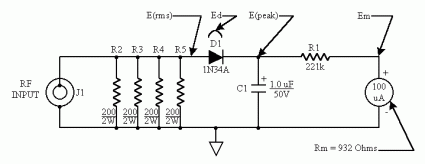
The basic QRP watt meter is a combination of a dummy load, and a simple rectifier/capacitor circuit in parallel. The dummy load provides the appropriate 50 ohm load, and the diode rectifies the code, converting it into a DC current, which is then used to charge a capacitor. If you measure the voltage across the capacitor, you can compute the power pretty simply. Power in watts is just Voltage squared divided by resistance, so if you square the voltage and divide by 50, you get the power.
Yes, yes, this isn’t quite right. I haven’t taken into account the voltage drop of the diode, but let’s run with this.
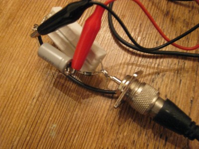
So, I went into the junk box (which I’ve been trying to add stuff too, dug out a rectifier diode, one of my larger 8ufd caps, and a pair of 10w, 100 ohm resistors (more on this later). I also dug out an SO-239 socket that I picked up from Radio Shack. Here’s the resulting gadget.
Using my cheap old Radio Shack digital multimeter, I clipped some test leads to measure the voltage between the diode and the ground. I took a 1 foot cable, hooked the load to my FT-817, and tested it out. Setting the FT-817 to its max power level, I turned on the transmitter and measured the voltage. I got a reading of 19.2 volts with this (essentially non-existant) cable run. If you multiply this out, we get 19.2*19.2/50 yielding about 7.372 watts (a bit higher than the nominal 5 watts that the FT-817 lists, but we’ll get back to that later). On its low setting, the voltage read right around 6 volts, yielding about 720mw.
Allright, that’s my baseline. I then took the dummy load outside to the far end of my cable run, and hooked it up there. The results were 17.8 volts (yielding 6.337 watts) and 5.5 volts (yielding 605mw). How does that compare with the nominal result we’d expect from RG-58 over a 50 foot run on 40m? The coax calculator can tell us. Plugging in 50 feet of RG-58 with an SWR of 1:1 on 7.07Mhz and an input power of 7.37 watts, we find we get about 0.5db of loss, and an output power of 6.587 watts. Similarly, if our output power was 720mw, we’d find about 643mw as the output power. That’s pretty darned close to what we expect from RG-58.
So, my conclusion is that my coax, while not the greatest stuff in the universe, isn’t a complete dummy load. If I’m going to blame my relatively poor recent performance, I’ll have to look elsewhere for a scape goat.
Okay, here’s some open questions. First of all, the resistors I chose. They were $0.99 at Fry’s, but their body seems to be made out of some kind of ceramic. There is a possibility (even a good one) that these resistors are internally wirewound, which means they aren’t necessarily entirely resistive: they could have an inductive component. Does anyone have any experience with this sort of resistor? Should I find some others?
Secondly, I didn’t account for the voltage drop for the rectifier diodes. The diodes were something that I dug out of my junk box, and I’m not even sure what type they are. I imagine they have somewhere between 0.5v and 0.7v drop. Technically, this means that the voltage measured at the cap is low by that amount, so the power should be a bit more.
Thirdly, I am confused by the values that I got. Especially considering the above, these power values seem much higher than the nominal values that we are supposed to get from the FT-817. The nominal maximum power should be 5w. I am suspicious that we are mixing peak and RMS voltages/powers here, since the values that I got are almost exactly sqrt(2) off from the values that I might expect, but I haven’t worked that out entirely in my head yet.
Anyway, that’s enough for today.
Addendum: This site has a circuit which is essentially what I built (different diode, and I am using a volt meter, rather than a current meter). It does indeed seem to indicate that the voltage that I’m reading out is the peak, not the RMS voltage. I’ll have to think about it some more.
Addendum2: Wes Hayward, W7ZOI has a writeup based upon the exposition in EMRFD which would be good for me to understand.
Addendum3: Yes, the resistors are probably wirewound (these cement power resistors apparently almost all are). I’ll have to go find some 200 ohm, 2 watt resistors to gang up in parallel.
Addendum4: I can’t stop! Another potentially useful link for measuring low powers, might be useful when I get to my QRPP beacon project.
Comments
Comment from Mark VandeWettering
Time 4/11/2009 at 11:34 am
Bill:
True, but I measured them with my antenna analyzer. They are essentially pure resistive at 7.00 Mhz, and even up through 10m have really minimal inductance.
Comment from Bill
Time 6/3/2009 at 3:27 am
Looks like a power supply circuit to me.So is it 1.44 or .7 times the input voltage at the output?Also the rf leakage from the socket into the meter and wires could upset the results.Shielding is a good idea when measuring rf powers.Some rf can be rectified at the contact point on the meter sockets if the probes are corroded.Just a thought.
Bill
vk2iva
Comment from Paolo
Time 3/4/2010 at 6:33 am
I built a similar device using two 100ohm/5W resistors in parallel. The MFJ-259B analyzer shows they are usable up to 30 MHz with 1,2:1 SWR and 1,5:1 @50 MHz.
Given I had scrounged those resistors from an unused board, the price pays for its inaccuracy.
See N5ESE page on “RF Probe” for some hints to adapt the resistive measuring network to read RMS on your DVM.
ik1zyw
Comment from Jason Trevino
Time 11/19/2016 at 3:11 am
Great article. I think you should test by a good digital multimeter. Thanks for sharing.


Comment from Bill
Time 4/11/2009 at 11:26 am
Those look like wire wound resistors, which are inductive and should not be used as an RF load. This might explain your unexpected measurement results.
Vy 73
Bill N4BKT