The Tale of Two Meters
Well, I’ve been mucking around with my RF probe circuitry a bit tonight, and encountered something pretty strange. I have two digital multimeters lying around, and my newly rebuilt RF probe/dummy load that I described earlier. I hook one multimeter to it, and I get a reading of 14 volts. I get my other cheapie meter, and I get a reading of about four volts. Yet, both are probably “correct”. How can that be?
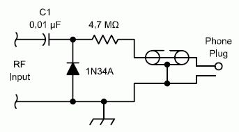
Well, first, let’s review the circuit that I have revised to:
I have used a different diode (a 1N914, which is probably better than the 1N4001 that I had in there previously, but not as good as the germanium diode you see in the schematic) and didn’t have any 4.7M ohm resistors, so I hooked two 2.2M ohm resistors in series. The voltage drop for the 1N914 is probably about 0.7 volts, but haven’t measured it. The purpose of the 4.7M ohm resistor is to convert the peak voltage (as gathered in the capacitor) to RMS voltage. How does this work? Well, if you imagine that the meter has some input resistance, then we basically have a voltage divider: the voltage that is measured by the voltmeter is the peak voltage, multiplied by the resistance of the meter divided by the sum of the meter resistance and the 4.7M ohm resistor. In years past, where this design was first put out, the common impedance for meters was around 11M ohms. So, the voltage we get out is the peak voltage * 11 / (11+4.7) = .7006 * the peak voltage. The peak voltage is sqrt(2) times the RMS voltage, so the RMS is the peak divided by sqrt(2). 1.0 / sqrt(2), which is .7071 or so, so the 4.7 Mohm resistor would be about right for a voltmeter with 11M ohm resistance.
Reading up on the subject, modern digital volt meters have an input impedence of 10Mohms. To figure out what size of a resistor we need for that, we solve 10 / (10 + R) = 1/sqrt(2) for R, and we end up with about 4.1M ohm resistance. I ended up approximating this by two 2.2M ohm resistors, which is closer, but still not perfect.
Okay, so that’s my thinking. So, I jumper the thing to one of two meters, and get a reading of about 14 volts. This indicates an output power of 14*14/50 or 3.92 watts (this was my FT-817 in 5 watt mode). The number is small, but I expected that. I haven’t accounted for two things: either the voltage drop of the diode, nor the problem with using the wrong series resistors. Instead of dividing the peak by the sqrt(2), I am multipling by about .694. Still assuming a 10M ohm resistance, my 14 volts should have been about 14.17 volts, plus the voltage drop (say .7 volts). This works out to about 4.42 watts. In the right ballpark, given that we didn’t really measure the impedence of the meter.
But here’s the odd thing! I hooked it to another, cheap meter of mine, and got only 3.92 volts! This is a budget DVM, which probably cost me about $10 that I have used mostly to check to see if my car battery is dead, but the difference is startling. The only conclusion I can draw is that the cheaper meter has a dramatically different impedence, probably around 0.5 Mohms. To test this idea, I measured the peak voltage at the junction between the cap and the diode, and both meters were in agreement. Interesting!
Through a coincidence, WB8ICN has been examining the same issue on QRPedia. He suggests using a potentiometer hooked to a regulated power supply, and measuring the voltage as you adjust the potentiometer until it reaches half the supply voltage, then the potentiometer is set to the impedence of your meter. Of course, with a little algebra, you don’t need to do that: you can just measure the voltage drop of any resistor with a resistance of a 1M ohm or so, and work it out. I’ll probably do that for both my meters, and then stick a little note on them so I remember.
Oh well, that’s my electronics tinkering for the day.

I recall burning three or four weeks of a sabbatical getting Saccade.com on the air with Wordpress. So much tweaking…