Or more precisely, is it oscillating, or is it not oscillating?
This is my first attempt at actually trying to build a circuit using Manhattan style construction (so please, be kind!) I fetched the oscillator circuit from EMRFD, and tacked it together with some parts from my junkbox. The only substitution that I made was that the two 390pf capacitors were replaced with 220pf capacitors. My understanding (limited as it might be) is that this is parallel capacitance for the crystal, and should move the oscillating frequency somewhat closer to the frequency of the crystal (in this case, 7.040 Mhz) than the specified design.
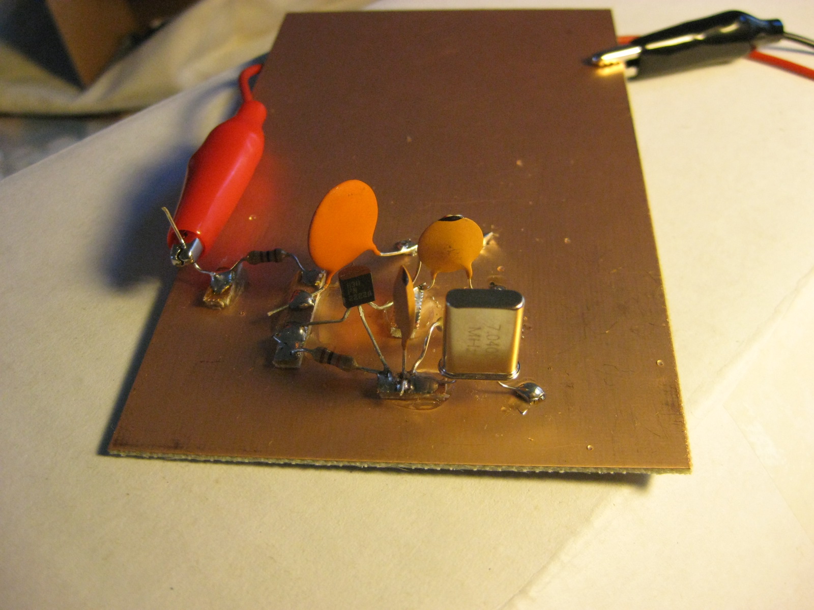
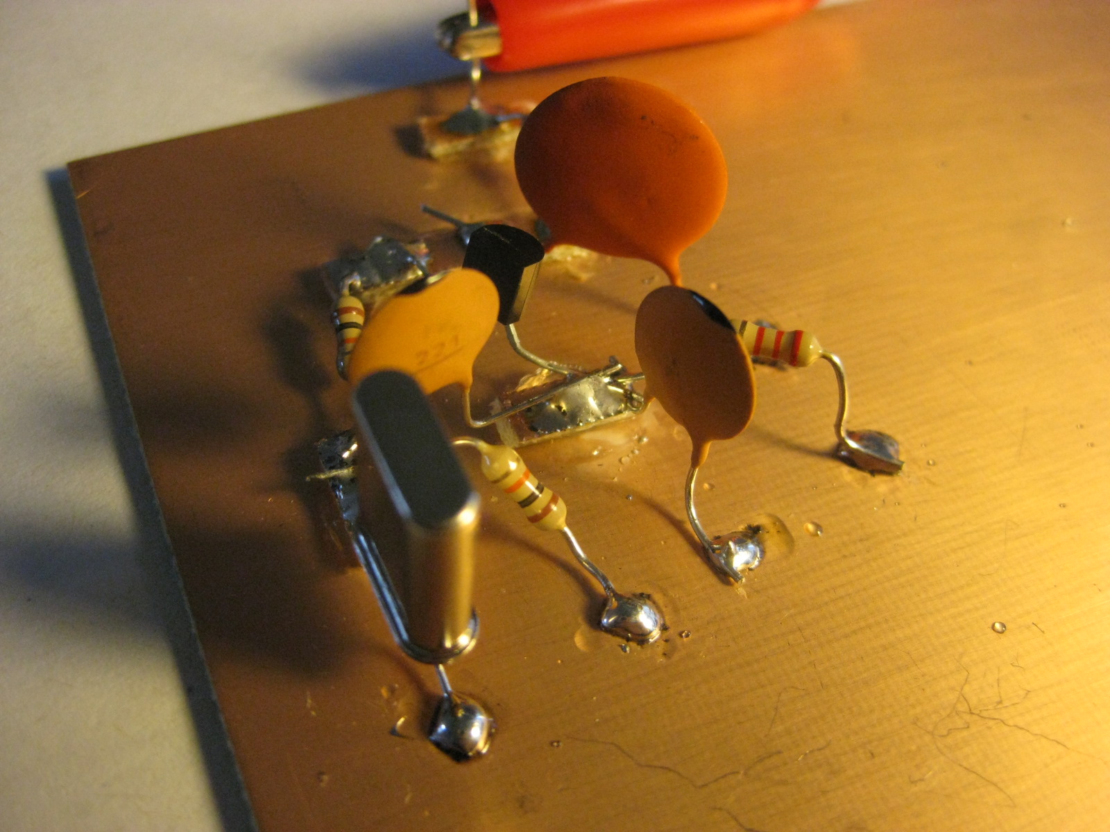
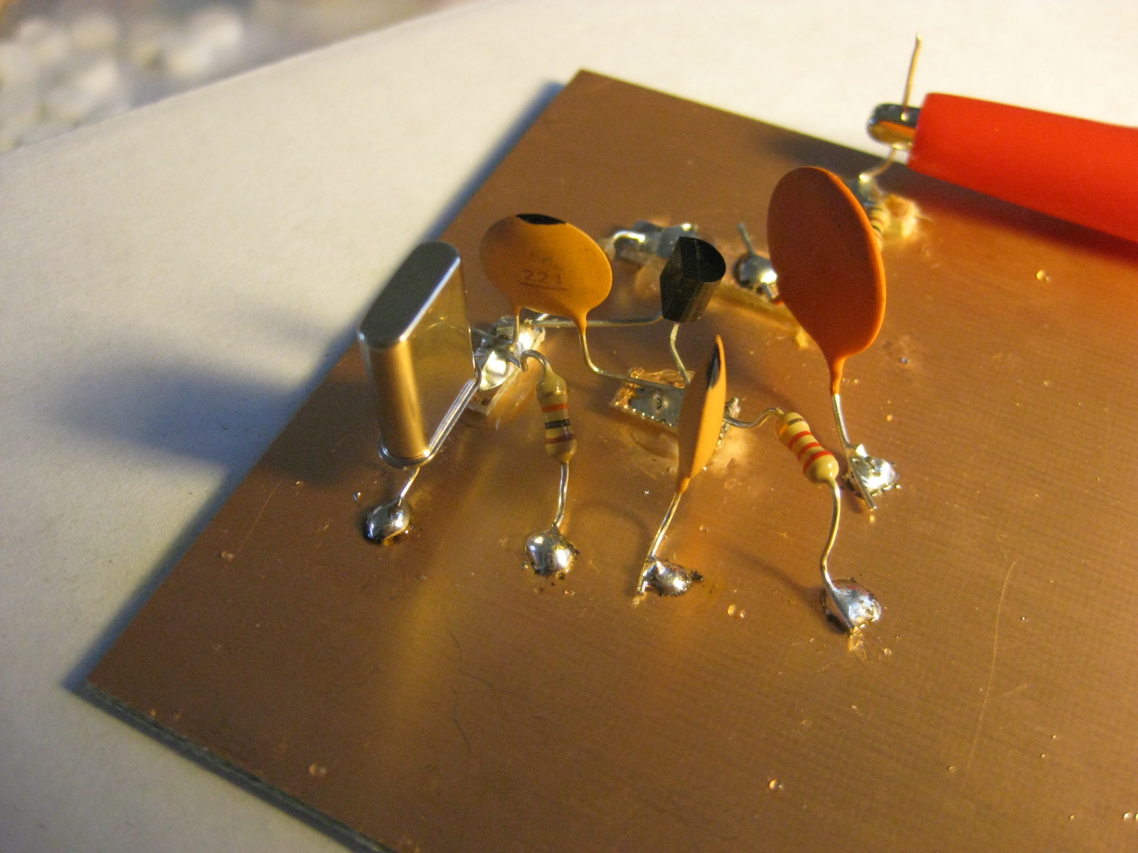
Here are some photos:
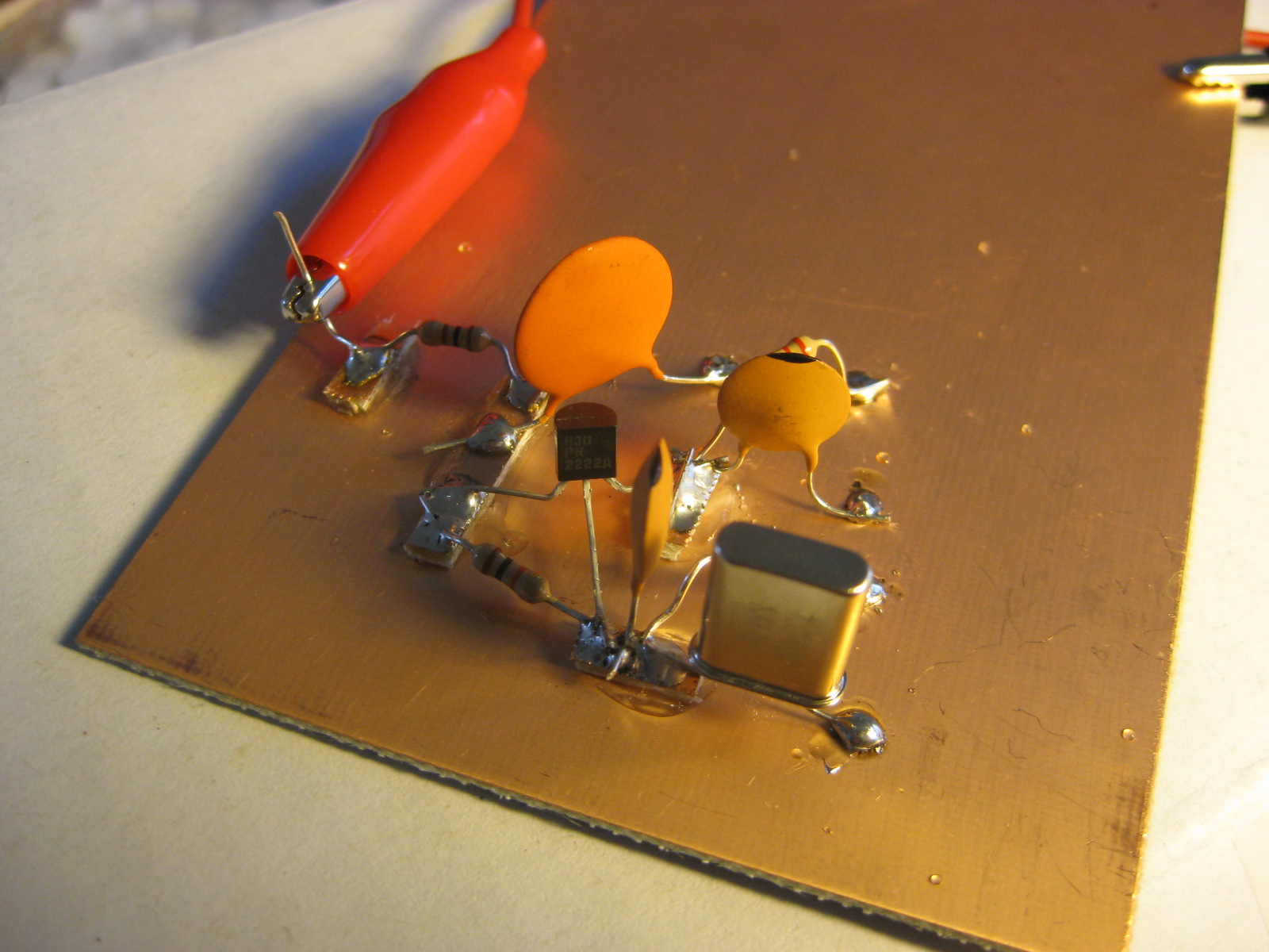
EMRFD says that this should oscillate at very low voltage levels, so I powered it up with a 9 volt battery. No magic smoke was released, but fishing around the design frequency using my FT-817ND, I heard nary a trace of it anywhere near the design frequency. If I had an oscilloscope, it would probably be pretty easy to tell, but I don’t (hey, I told you I was new at this). I fished around with my multimeter a bit, measuring continuity and the like. The overall resistance between the positive voltage supply and ground is about 19k ohms, indicating an overall current draw of about 0.4ma (with the 9 volt supply). That seems low, but maybe not excessively low. Measuring the base voltage on the transistor, I get about 3.35 volts. Again, that seems reasonable to me.
For all I know, it could be oscillating, but at a low power level. I’d rather not proceed building the buffer amplifier until I was reasonably sure the oscillator was working. Any ideas, oh wisdom of the internet?
Addendum: On a whim, I swapped out a color burst crystal (3.579Mhz) and it started to oscillate. As i tough various components, I get a stronger signal, but relatively little frequency shift.
I’m hypothesizing that my substitution of the 220pf for the 390pf ones wasn’t entirely kosher.
Addendum: Here’s some video:
Addendum2: Heh. I think the transistor was in backwards. Reversing it, and it now oscillates on 40m. Thanks to Eldon Brown for the suggestion, which made me double check. Next stop: a buffer amplifier!
Addendum3: It oscillates at 7.038616 Mhz or so.
If you don’t have an oscilloscope, one of the cheapest and easiest ways to confirm the presence of RF is that RF probe that you built earlier. You should have enough RF voltage from the crystal oscillator to get a decent reading from the probe if the circuit is indeed oscillating.
I see that you also found that the two capacitors in the feedback network can be touchy. Generally speaking, in a Colpitts oscillator, you should try to stick as close as possible to the values given for these two components. You might want to try paralleling another 220 pF cap across each of your originals to get it to 440 pF, which is a lot closer to the 390 that is called for.
I think you have the transistor backwards??? That is if it is a 2n3904???
I know I did on the first try.
If you didn’t have the RF probe, the following idea might work. Place a cap on the oscillator output to remove any DC component, then depending on the voltage of your output a small resistor to limit current, followed by an LED to ground. If you have oscillations, I think this little series circuit should cause the LED to light up.
Ciekawy blog, dodalem go do ulubionych, bede tu napewno wpadal czesciej
Hey man,
I intend on building my first oscillator soon
this is great encouragement to see an
oscillator working with so little components.
Would you please be as kind as to post a schematic
of the circuit that you built above?
I dont have access to EMRFD (:
Thanks for sharing,
73 from Ireland