I recall burning three or four weeks of a sabbatical getting Saccade.com on the air with Wordpress. So much tweaking…
Common emitter amplifier design using ngspice…
Okay, I’ve been reading some of my variou sources on amplifier design including EMFRD and the ARRL Handbook, and decided to try to test my understanding of them by coding up a simple common emitter amplifier, and then testing the model by plotting out the voltages using ngspice, the open source version of the popular Spice code that runs on my linux box. Normally, you’d use a schematic editor to create the circuit, then compile it to a net that spice can read. But for simple circuits like this (and by looking at the examples on All About Circuits, I didn’t find it hard to just type in the model by hand. I don’t have too much time to go into the details, but here is the code:
# a common emitter amplifier design by Mark, K6HX

# mostly as a tutorial for using ngspice

vin 1 0 dc 3

vsig 2 1 sin(0 .316 10140000)

vcc 3 0 dc 13.8

r1 3 4 27350

r2 4 0 2650

Cin 4 2 10uf

Q1 5 4 6 mod1

Rc 3 5 1780

Re 6 0 220

Cout 5 7 10UF

Rload  7 0 5MEGA

.model mod1 npn

.tran 0.004u 0.12u

.plot tran v(2,1) v(7)

.end
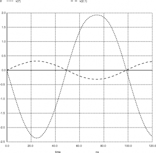
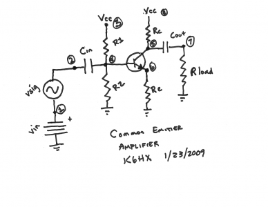
The signal is a 10Mhz sinusoid (I’m eventually interested in making a 30m beacon). The vin voltage source is a dc offset, which basically gets stripped by the Cin capacitor. The signal is then biased by the resistive divider formed by R1 and R2, and then fed as the base voltage into Q1. The gain is approximately -Rc/Re, in this case very close to approximately -8. The voltage is measured across a 5Mohm resistor (modelling the internal impedence of a meter, I just picked 5M ohms at random, mine is closer to 9.18Mohm).
Anyway, here is the plot of the input signal (the smaller amplitude) and the inverted output signal.
I’m learning a lot.
Addendum: Here’s the schematic, drawn with a sharpie on a napkin:


Comment from NM5DV
Time 1/23/2009 at 2:10 pm
Is there much difference beetween ngspice and ltspice ?
Maybe you could post your file so I could play with it.