A Half Wave Filter in LTSpice
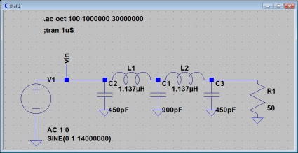
On page 3.4 of Experimental Methods in RF Design, they have a little side bar about a particularly simple form of harmonic filter that I thought I would try to analyze in LTSpice. Here’s a screen dump of the filter I designed to operate around 7.0Mhz.
It’s really pretty simple to figure out the value of the various components: if the load has a reistance of Rload, then the inductors both have the same reactance XL in ohms. The two outside capacitors also have that same reactance, while the inner one has twice the value. Combined with the formulas for the reactance of an inductor and capacitor, it isn’t hard to figure out the values.
XL = 2.0 * π * frequency * L
XC = 1.0 / (2.0 * π * frequency * C)
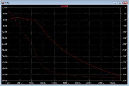
Performing an AC analysis, you can get the frequency response. You can see that this filter actually passes the design frequency at 0db, but is significantly attenuated at 2x the frequency, and even more so for higher multiples. Here is LTSpice’s simulation.


I recall burning three or four weeks of a sabbatical getting Saccade.com on the air with Wordpress. So much tweaking…