I recall burning three or four weeks of a sabbatical getting Saccade.com on the air with Wordpress. So much tweaking…
Power Transfer Math
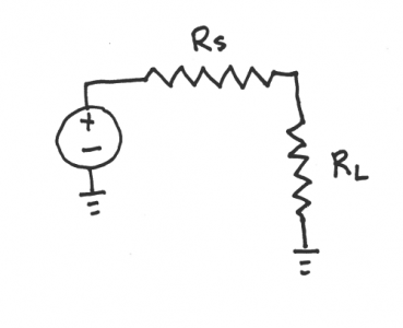
As I might have mentioned, I am trying to teach myself a bit about electronics and radio design. I find the problem with being self taught is that often you read something, and it doesn’t seem clear to you why it should be so, and you uncover the basic lack of understanding that you have to go back and fill in before the later material makes sense. This happened to me while I was trying to work through some more amplifier designs, and I realized that I had a basic misconception about how impedance matching actually worked, and this was perhaps even more basic, and could be illustrated with a simple circuit, consisting of a voltage source, and then in series a source resistance RS and a load resistance RL. The question is given an RS, what value of RL maximizes the power dissapated in the load RL?
Well, it’s not really too hard to figure out. First, we can determine the total current going around the loop. For a voltage V, the current is simply:
       V
I = -------
    R  + R
     S    L
From this we can easily determine the voltage drop across RL:
      R  V
       L
V  = -------
 L   R  + R
      S    L
And, since we know the current through and the voltage across the resistor, we can determine the power as their product:
            2
        R  V
         L
P  = ----------
 L            2
     /R  + R \
     \ S    L/
When is power maximized? Well, we can differentiate the power equation with respect to RL, and we get:
                           2
dP         2         2 R  V
  L       V             L
--- = ---------- - ----------
dR             2            3
  L   /R  + R \    /R  + R \
      \ S    L/    \ S    L/
Setting this equal to zero, and solving for RL, we find that a maximum occurs where RL equals RS, in other words, power is maximized when the source and load resistances are matched. The total disappated by RL is then:
      2
     V
P  = ---
 L   4 R
Thus, if we had a load of 50 ohms and a voltage source of 12 volts, we’d end up with a maximum power of 720 mw.
Addendum: As a double check, the power passing through both resistors is V^2 / 2R, which would have been 1.44 watts, and obviously since both resistors are the same, the power is evenly split between the two.
Addendum2: I forgot to mention what I was confused about. It’s not really this (which occurs in DC circuits) but the corresponding circuit which occur in AC circuits with complex impedances. I’ll work through this later.
Addendum3: Hmm. Subscripts and superscripts seem to not work right with this theme. I’ll fix it.
Comments
Comment from Suraj
Time 12/7/2009 at 10:07 pm
For AC circuits, think of capacitors and inductors as Yin and Yang. You need a balance between those to transfer maximum power 🙂
Comment from Kevin
Time 12/8/2009 at 11:32 pm
To understand load matching and impedance problems, it would be good for you to understand Thevinen and Norton equivalents.

Comment from Kenneth Finnegan, W6KWF
Time 12/7/2009 at 3:28 pm
Interesting post. Had to do a lot of this type stuff in my college circuits class, and I was sure glad I already had some idea what was going on, thanks to my license.
Some pointers on notation if you haven’t seen them before:
You can use the sub and sup tags to make sub and superscripts, so you can write RL as R”sub”L”/sub”, replacing the ” with less than and greater than signs.
For the most involved equations, I will type them up in LaTeX and render them as pngs, but an easier way is using an online tool like Sitmo: http://www.sitmo.com/latex/
Example equation: http://www.sitmo.com/gg/latex/latex2png.2.php?z=100&eq=V_L%3D\frac{R_L%20V}{R_S%20%2B%20R_L}