I recall burning three or four weeks of a sabbatical getting Saccade.com on the air with Wordpress. So much tweaking…
Tank Circuits…
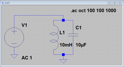
Okay, time to work my way through some more complicated (but stll simple) examples. First of all, let’s consider a simple parallel LC circuit. Here is one with a 10uF capacitor and a 10mH inductor in parallel with an AC source:
We can compute the resonant frequency using the classic formula:
          1
f = ------------
        __   ___
    2.0 || \/L C
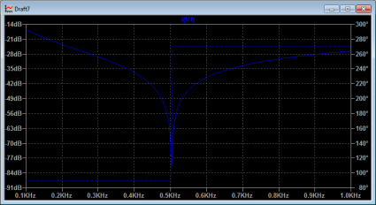
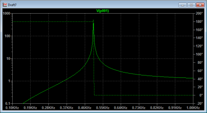
Plugging in our values for L and C, we end up with a resonant frequency at approximately 500 Hz (more precisely, about 503 Hz). So, let’s use LTSpice to analyze the circuit using AC analysis, sweeping the frequency from 100Hz to 1000Khz. If we look at a graph of the current draw through the voltage source from this parallel LC circuit, we see the following:
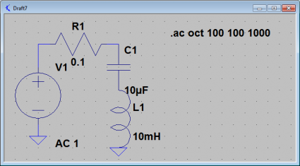
The parallel LC circuit’s current draw drops to zero at the resonant frequency. It’s impedance goes to infinity at the resonant frequency, the tank doesn’t draw any current. Let’s compare it to the same circuit, but with the elements placed in series instead of in parallel. We’ll add a very tiny resistance as well.
This circuit also resonates at the same frequency, but with radically different behavior. Let’s graph the current in this circuit:
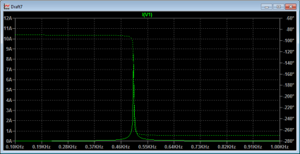
The currents through the circuit are huge, and peak at the resonant frequency. There are similarly huge voltages that appear across the capacitor.
All this is pretty basic stuff. I apologize for boring people with this, but I’m learning lots about using LTSpice by doing these basic exercises. It’ll eventually pay off by having a deeper understanding about how these circuits work.
Addendum: I was inspired by this chapter on resonance from Tony Kuphaldt’s second book on AC electric circuits. These books are part of the Open Book Project, and are available for free download. I’m gonna make good use of these.
Comments
Comment from Kevin
Time 12/9/2009 at 12:04 am
Significant levels of resistance are introduced into real world tank circuits. So much that the theoretical formulas are invalid.
Resistance in parallel with L, for example, will cause a real world shift in the frequency of your series or parallel resonant filter.
Maybe calculations have improved to predict these outcomes more reliably than technical school from 30 years ago, but I think largely engineers are relying on the FM principle for developing reliable tank circuits.
It’s Freaking Magic. 😉
Comment from Dan Lyke
Time 12/8/2009 at 12:52 pm
Thank you for learning in public, it’s good for me to pick this stuff up by osmosis.