I recall burning three or four weeks of a sabbatical getting Saccade.com on the air with Wordpress. So much tweaking…
Modelling the NT7S code practice oscillator with LTSpice
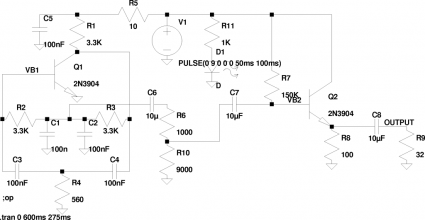
As I was chatting on the QRP Echolink conference tonight, the subject of code practice oscillators came up. I think it was Bob, AD7BP who first mentioned the NT7S Code Practice Oscillator which I hadn’t seen before, but seemed like a very simple and easy to assemble circuit. We also discussed the fact that the latest issue of QST has started to use LTSpice in their Hands On Radio column. As I was waiting for my turn at the round table, I went ahead and entered the circuit into LTSpice to see how it worked. Here’s the schematic I came up with.
Go ahead and click on it to make it bigger. There are some small changes. I went ahead and added a load resistor R9 (I set it to 32 ohms here, with the idea that the oscillator would be hooked to a set of low impedance earphones) and instead of modelling the key switch, I instead powered it with a pulsed voltage. I was mainly interested in seeing what the shape of the output signal was, so I set it up to a transient analysis. Sure enough, it generates a nice sine wave. I set the input pulses to be about 50ms long, which should be about the same as the dits at 24wpm.
Here’s the resulting simulated circuit:
Running an FFT on this output data shows that the oscillator frequency is right around 680 Hz, with an output power of about 0.5mw, and the second harmonic over 20db down, and the 3rd harmonic 30db down. I’d say that qualifies as a pretty reasonable waveform. I thought that the output power was a bit low, but the oscillator is normally used with either ear buds, or with an external amplifier. I suspect it will work reasonably well.
It was a fun experiment in using LTSpice.
Addendum: It dawned on me that simulating the keying by pulsing the input voltage wasn’t entirely correct: in the original circuit, the keying is provided by grounding the 560 ohm resistor, while power is continuously applied. Even intuitively, one might see how that makes a difference, because various capacitors in the circuit will remain continuously charged. This morning, I decided to go back to a straight DC power supply for Vcc, but then installed a small switching transistor between the 560 ohm resistor and ground, and fed <em>that</em> with a pulse through a current limiting resistor. The waveform cleans up a bit at the beginning: we have a nicely shaped ramp up, without the overshoot that we saw previously.
Addendum: I was wondering if I could use this information to find out what this circuit would really sound like: in other words, I wanted to convert the raw LTSpice output into a .WAV file that you could play back on your PC. It turns out that LTSpice can export the waveform in an ASCII format, which includes a bunch of lines which have two numbers: a time, and a value. The slightly annoying thing is that the times are not evenly spaced. So, I wrote a tiny chunk of Python that takes in this file, and resamples it to evenly spaced times. I write this out again as an ASCII file, adding a small header so that the “sox” sound utility can read it, and convert it into a wav. I then use my normal “lame” command line mp3 encoder to convert it into an mp3 file.
The following sound file was converted from the real data, and consists of three groups of ten dits, sent at 24 words per minute, with some space in between:
Simulated sounds of the NT7S code practice oscillator
I also found out that sox can actually draw spectrograms of wav files. It’s not quite as versatile as the homebrew code that I wrote, but it works. Here, the individual dits kind of run together, but it shows that the second harmonic is at least 40db below the primary frequency, so the dits are pretty clean:


Comment from Jason Milldrum, NT7S
Time 12/31/2009 at 4:11 am
Wow, you’ve done some great work here Mark. Your code-fu is most excellent! I always enjoy seeing people take something I’ve worked on and then analyze and extend it. I’ve also heard that someone has adapted the CPO to plug into their PC audio card for EchoLink CW. Neat stuff, keep up the great work on your blog.
73,
Jason