Simulating a phasing radio…
I’m gonna dash off to an appointment with my tax guy in a few minutes, so I’ll have to be brief. I’ve been reviewing literature on inexpensive/simple phasing double sideband and single sideband transmitters. It dawned on me that while it was pretty simple to generate the necessary quadrature signals for the carrier frequency (the solution that most people use is to generate a carrier at 4x the desired frequency and then divide it in quadrature with flip flops) that such a solution wasn’t really that neat at audio frequencies. To get good opposite sideband cancellation, you need to generate a very accurate 90 degree phase shift for the incoming audio frequencies. This seems tricky. Fussy.
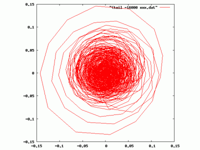
But, of course if you have some compute power handy, it isn’t really that big of a deal. You can use something called the Hilbert transform which does precisely what you want. From a given signal, it generates the quadrature signal that you need. If you plot the input versus the output for a constant amplitude signal, you get a nice circle, precisely in phase. If you apply it to a voice input signal with varying amplitude, you get a series of circular spirals, like the plot below.
It is probably only an hour or so work to generate a complete abstract implementation of the phasing transmitter/receiver. That’s coming, and I’ll document it more here and make the code available for the interested. Till then, wish me luck with the IRS.
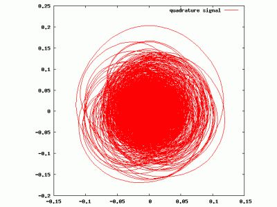
Addendum: Tax appointment went as well as could be expected. I didn’t like the straight lines in the digital signal above, which game from its relatively low sampling rate. If you upsample the signal with a high quality, band limited up sampler, you get a much smoother result, as can be seen below (the audio input wasn’t quite the same, so it doesn’t look exactly the same):


I recall burning three or four weeks of a sabbatical getting Saccade.com on the air with Wordpress. So much tweaking…