Simulating a 40m bandpass filter in LTSpice
A few days ago, I created a small program to compute bandpass filters using the equations from Experimental Methods in RF Design. Basically, you can pick a given inductor value, and then it solves for all the necessary capacitors. What wasn’t immediately obvious from the equations and the values that are generated was how these values interacted to alter the shape of the filter, and how variations in their value (perhaps to match easy to find capacitors) could change the frequency response.
So, I decided to go ahead and play with it using LTSpice.
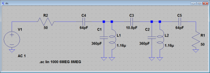
Here’s an example filter that I got by specifying a 7.1Mhz center frequency, with a 250khz bandwidth. The source and load impedance are both specified to be 50 ohms. Using the program that I posted before, I got the following component values:
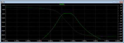
I then could go ahead and simulate the filter using LTSpice’s AC analysis, which yielded the following frequency response:
It looks pretty good. Using LTSpice, it’s pretty easy to check how (for instance) variations in the source or load impedance change the shape of the filter, or how small variations in the value of components affect the losses.
One thing that I didn’t immediately figure out was how to employ the inductor Q. LTSpice doesn’t include a place to enter Q, but it’s easy to compute the necessary parallel resistance (it’s just 2.0 * pi * F * L * Q) which LTSpice can use.
I really need to build one of these for the DC40B.


I recall burning three or four weeks of a sabbatical getting Saccade.com on the air with Wordpress. So much tweaking…