I recall burning three or four weeks of a sabbatical getting Saccade.com on the air with Wordpress. So much tweaking…
The K6HX Arduino QRSS Beacon (ala Hans Summers, G0UPL)
So, today I drove down to HSC in Sunnyvale and got (among other things) some trimmer capacitors so I could tune my beacon, and when I got back, I set to work. I pulled the 22pF capacitor and put in my trimmer, and then hooked up my SDR-IQ receiver to the laptop so I could see where the radio was tuning. A few tweaks with a screwdriver (wish I had a non-metallic one for this) and I got it centered in the band between 10.140Mhz and 10.140100Mhz. It seemed to stay there pretty well. I had previously made a simple input filter on the board (consisting of a 10K resistor, and a 22uF capacitor (too high, but it was what I had on hand). I wired it up through a 1M ohm resistor (as per Hans’ schematic) and then took the voltage from the two AA supply (let’s call it 3v, even if it is really somewhat less) and tapped it into the input. Sure enough, the radio tuned up about 40Hz. When I removed it though, the filter drained really slowly, returning to its original value only after twenty seconds or so. I thought this was going to be a problem, but then I realized that the filter capacitor had to discharge through the 1M ohm resistor, because the input was floating, but when hooked to my Arduino, it would would discharge back to the ground inside the Arduino through the 10K resistor, which would mean that it would discharge 100x faster. That seemed to work out in practice as well.
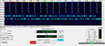
But my first test was simply an unfiltered test: sending either the high or low value to an output pin, and sending it into the modulation input of the beacon. To generate the keying waveform, I just modified my earlier Arduino Morse Beacon to send at 1 second dits, and then used Spectravue on my SDR-IQ to scan a relatively small (500hz) bandwidth. A few seconds later:
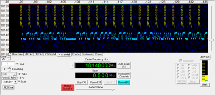
I then tried sending the input through the smoothing filter. As you can see, the waveforms now look fairly rounded:
But the Morse is still clearly legible. I decided to leave the input filter as it was, since in QRSS3 mode, the dits would be 3x longer. Measuring the overall frequency deviation, it seemed like it was about 50 or 60 hertz. Rather than setting up a pot as a voltage divider, I instead programmed the Arduino to vary its voltage between 4 and 5 volts, which I figured would give me 1/5th the total deviation, or about 10 hertz. And… it works! Witness the absurd and poorly lit video, demonstrating reception via my FT-817 and Spectran, but still transmitting into the same 50 ohm resistor at the lowest power setting (I suspect right around 2 or 3 mw).
Bill, N2CQR will probably appreciate that initially, I seemed to be generating upside down Morse as well. I modified the program to flip the Morse around, and all was well. But then I moved this radio to hook it up again, and the Morse code seemed upside down again. So, I flipped it back. All is well. For now.
I was concerned about the stability, but it seems pretty good, considering that I just used the crappy stuff from my junkbox. Eventually, I’ll get it in a box to keep the temperature more stable, I’ll make some software improvements (perhaps sending Hellschreiber) and then get it on the air.
73 de K6HX
Addendum: Here’s the link to Hans’ design. Thanks Kenneth, for reminding me that I had forgot to link to the schematic. Click on “Construction”.


Comment from Kenneth Finnegan
Time 2/12/2011 at 10:56 pm
Very cool and interesting watching your progress. I’m looking forward to seeing a complete schematic for your transmitter, unless I just wasn’t able to find it on Han’s website? His QRSS beacon seems much more involved…