Monthly Archives: May 2011

Lotte Reiniger’s Adventures of Prince Achmed

Today, while scanning around for things that I could watch on Netflix streaming, I found that they had The Adventures of Prince Achmed, which was a movie which I had heard about, but had never seen. Wikipedia claims that it is the oldest surviving full length animated feature film, dating back to 1926.

I first heard of this film back when I was in grade school, and I developed an interest in puppetry, and in particular shadow puppetry. Reiniger wrote a book entitled Shadow Puppets, Shadow Theaters and Shadow Film which was published in 1970, and which I checked out from our local library multiple times. I have never seen a live shadow puppet performance, but her book was intriguing, and I retain an interest in the technique to this day. Just this weekend, I saw the new Kung Fu Panda 2 which has some introductory “flash backs” which are clearly inspired by Chinese shadow puppetry.

It doesn’t have anything to do with my usual blog fare, but it’s pretty cool stuff. If you have Netflix streaming, check it out!

Speleogroup’s cool LED headlamp design

Fellow hacker Mike Cowlishaw tweeted me a reminder that he had worked on a design for a spelunker’s headlamp that used Luxeon LEDs, and had excellent high performance. I remember that I listened to a talk about this design, but at the time, I wasn’t saavy enough in electronics to grasp the details, and it had slipped from my mind. He was designing a headlamp for caving, where battery life was a serious matter of safety, so efficiency was primary concern. The final design they came up with would drive a 350ma Luxeon LED at full power for over 5.5 hours using 4 high capacity 1800maH batteries, and then would automatically step down the current as the battery voltage faded. Their first designs used an LT1512A constant current/constant current battery charge controller, but the version I think most interesting was just a small Atmel AVR chip driving a IF7422 FETKY (combination power MOSFET and Schottky diode. Very neat! Mike references an interesting AVR application note which gives a complete design for a battery charger, which is indeed somewhat similar. I’m printing it out so I can read it later.

Speleogroup – LED Lamp based upon ATtiny

Thanks Mike!

A simple constant current LED circuit

I’ve been pretty happy with the performance of my linear current based LED transmitter, but that was just sitting on the bench, driving a 20ma device. As I played with the circuit, I began to realize that if I scaled the circuit up to a 1W LED, its deficiencies in terms of efficiency would become more evident. In particular, I began to think about the efficiency: what percentage of the total power delivered by the battery is actually consumed by the LED?

Rather than using my previous op amp circuit, I thought I’d analyze the basic circuit from this Instructable, which I’ve created and reproduced with LTSpice:

I substituted components: I used the every popular 2N3904 and IRF510, and entered a simple model for a 1W Luxeon LED, which has a current drop of around 3.4v. I set it for a 9v supply, just for an example. A quick simulation shows that current through the LED is about 285mA, which combined with the voltage drop means the LED is putting out about 973mw.

But there is also a voltage drop through the MOSFET and through the reference resistor R2. The resistor is easy to calculate: the current through it is the same as the current through the LED (285mA) and the resistance is 2 ohms. The voltage drop is the then .57 volts, and the total power is .57V * 285mA or about 165mw.

So, what’s left? Well, we began with 9v, and we drop 3.4 for the LED, and another .57V for the resistor, let’s say the total drop is 4V. That leaves 5V, and at 285mA or about 1.425 watts. Ouch. The total of non-LED components is about 2.6W, only about 1W of which gets to the LED which nets us about 37% efficiency.

We can do a bit better by lowering the supply voltage: dropping it to six volts lowers the current to around 267mA, but the voltage drop across the MOSFET decreases to just a little over 2V, which drops the power to about 550mw. The net result is the efficiency climbs to about 57%.

Of course now more integrated solutions exist: many of which combine voltage regulation and current limiting in very small packages at high efficiencies. For instance, the LM3407 is a 350mA constant current floating buck switching converter. It can achieve efficiencies of 90% over a wide variety of supply voltages in a very small, inexpensive package. It also appears that you can use it with a PWM input to implement dimmer technology. It seems like a chip like this can be the center of an efficient LED transmitter.

More to think about and play with.

Return Infinity – BareMetal OS

At various times, I’ve been interested in writing operating systems. I haven’t done much thinking about this recently, but it is a topic of interest. I hadn’t seen this project before: a small 64 bit kernel written in assembly. I have no idea whether it’s interesting, but I thought I’d bookmark it for future investigation.

Return Infinity – BareMetal OS.

FUNcube Dongle on order!

Huzzah! I’ve been wanting to get a Funcube Dongle Pro for some time, but they have been in short supply. Today, a fresh batch went on order, and this time: success!!

The Funcube Dongle Pro is a cool little software defined radio that plugs a USB port, and receives from 64Mhz to 1700Mhz. I am most interested in using it as a proper NOAA satellite receiver, but I have other applications in mind as well. Stay tuned for a review in the future when I get it in my hot grubby hands.

FUNcube Dongle | A radio that’s out of this world!.

Question about LEDs…

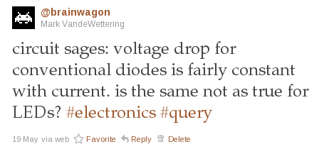
A few days ago, I posted a query to twitter regarding voltage drop in LEDs:

I didn’t receive a lot of truly helpful replies: a few people reinforced the general dogma that indeed LEDs were diodes, and since they were diodes, they should have relatively constant voltage drop despite current across them. But that’s not what I am observing with my simulations using LTSpice.

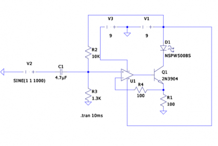
Here’s the schematic for my linear current based LED modulator more or less as I built it (for some reason the circles which define the voltage sources V1 and V3, as well as the simulated input signal V1 don’t show up, sorry ’bout that). The basic idea though is that the voltage appearing at the noninverting input of U1 is a 1V peak-to-peak audio signal, offset by 1 volt so the total range is 0 to 2V. The action of the op amp ensures that the voltage appearing at the top of R1 is the same as the noninverting input. Since the load is a constant resistance, that means the current is proportional to the voltage, and varies exactly with variations in the input voltage.

So, what are the voltage drops across the LED (D1) and the transistor (Q1)? My intuition says that the voltage drop across the LED should be (as per conventional wisdom) nearly constant. Looking at the datasheet for the NSPW500BS (a white LED manufactured by Nichia) I see that it lists a typical forward voltage of 3.6 volts (I picked it at random from the list of available LED models in LTSpice). So, what I would expect would be that the voltage drop across D1 would be nearly constant at 3.6 volts, and since the voltage drop across the load resistor mimics the input signal, that the drop across Q1 would look like 9V minus the audio voltage minus 3.6 volts.

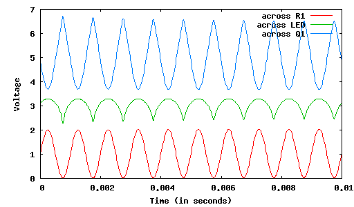
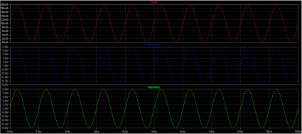
But here’s what LTSpice produces:

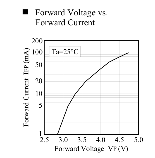
You can see that the voltage across D1 varies by nearly a volt. I tried replacing D1 with a more conventional diode (such as as a 1N4148) and the variation is much smaller (maybe 0.1V). Digging into the datasheet for the LED, I found this diagram:

Which does seem to imply that over currents of (say) one to twenty milliamps, the forward voltage drop may be a volt (and more, if you push more current through them).

So, here’s my question: is that typical of LEDs? Or maybe just white LEDs? And the more broad question: how can I translate information from the datasheet of an LED into a usable model for LTSpice so that I can realistically model this behavior?

More light transmitter experimentation…

Today, I had to do some yardwork, so I dusted off the weed whacker, and climbed the back of the hill to chop down some high grass. At the end of an hour, I was about 40% done (I’ll do the rest next weekend) but sneezing and coughing from the liberated pollen and dust. So, I called it a day, made a mental note to get a dust mask for next week, and showered.

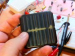
But while I was chopping grass, I located an old solar powered LED light that had been lost among the tall grass. It was probably three or four years old, and covered in dirt and dust. The solar cell in particular looked like some water had gotten in it.

The perfect organ donor for an improved receiver for my LED transmitter, thought I.

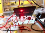
And it is. I disassembled the light, snipped the LED panel out, and soldered it in place of the LED that I was using in place of my receiver previously. And, not surprisingly, it works better. A lot better! A lot louder. Over a greater distance. There is no real contest.

I tried to shoot some video of it, but my hands are simply too shakey (muscles twitching from operating vibrating machinery for an hour) and it’s unwatchable. But here’s a little MP3 file that will perhaps hint at some of the improvement.

Demonstration of solar cell as light receiver (MP3)

Addendum: I decided to go ahead and post some video. It’s still pretty shaky, but it’s a reasonable demonstration of what’s possible with a scavenged solar cell. Pardon for the relatively poor lighting: my office is lit by compact flourescent bulbs, and when they were all on, the 60 hz whine (which you can still hear despite lowering the light levels) was pretty irritating.

DIY FET/home-made transistor Scientific American June 1970

When I was still in grade school, I (and this will be a shock to my readers) spent a lot of time in libraries. Our library used to have a free bin, where they would toss things that they no longer wanted in their collection. One day, I came by and found a pile of more than two decades of Scientific American magazines. Being a bit of a science nut, I carted them home, and spent many a happy evening reading Martin Gardner’s Mathematical Games and C.L. Stong’s Amateur Scientist column. Stong’s column was really cool, and had great articles about building plasma jets, X-ray machines, diffraction ruling machines, and all sorts of other good stuff.

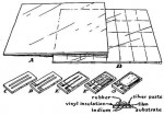
It was then with some suprise that I read Nyle Steiner’s article on making FET transistors from cadmium sulfide photocells, because he made reference to a 1970 article by Roger Baker that was about making home made FET transistors. I didn’t remember any such article. Luckily, I bought a CDROM which contains all the Amateur Scientist columns, and found it. And, indeed: it’s the second half of a two part column, and talks about the deposition of thin films. I guess I had never read it closely enough to see that it included the manufacture of a thin film transistor.

Here is a link to an online copy of the article.

The article also makes reference to THIN FILM MICROELECTRONICS: THE PREPARATION AND PROPERTIES OF COMPONENTS AND CIRCUIT ARRAYS which was available in preview mode on Google Books, and it seemed enticing enough that I decided to track down a copy via online search (I managed to find a copy for only $6 + $3.50 shipping). It seems like the level of this book might be within the reach of the dedicated amateur.

Good stuff.

A foxhole radio…

IRC and Minecraft buddies Atdiy and whisk0r have been doing some cool videos on making cigar box guitars, some kind of neural network stuff, and more recently: some introductory electronics videos. After winding inductors and making their own capacitors in previous episodes, they get around to making their own foxhole radio just using a blued razor blade as the detector:

Pretty neat! If you like this kind of stuff, subscribe to their YouTube feed.

LED Transmitter Schematic

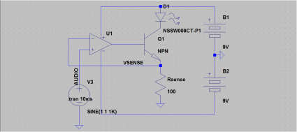
Okay, so here’s the schematic for the LED transmitter circuit as I assembled this evening. I tried to write up an exposition of how it works, but frankly, it pales in comparison to the clarity and completeness of KA7OEI’s page. But here’s the basic idea: imagine that you supplied 1V to the input of the op amp. The op amp will drive the voltage at the base of the transistor so the voltage coming off the Rsense is the same (1V). When that happens, the current through Rsense (and through D1) is just 1V/100 ohms (in this case) or 10ma. And, the current is linear in the input voltage: when the voltage rises to 2V, the current is 20ma, and when the voltage drops to zero, the current is zero. So all you really need to do is take a 1V peak-to-peak audio signal, offset it by 1V (which I didn’t show on the schematic, it’s just inside the audio source node), and it will generate the appropriate current.

It’s very cool, and requires very little math to actually design. And it doesn’t matter much what the transistor is either: KA7OEI’s page uses a power MOSFET, because he is driving a much more powerful LED, but for my purposes, using an ordinary 2N3904 worked just fine.

An improved linear current LED transmitter

I spent some time reading KA7OEI’s great article on creating a good linear current driver for an LED or laser based communication system. The basic idea was pretty straightforward, so I decided to try it out when I got home. The “simple” circuit that I had before was in no sense linear: the audio became severely clipped by the action of the LED. KA7OEI shows how you can use an operational amplifier to provide a linear current source. I’ll draw up the schematic in the next few days, but if you read his pages, you’ll probably find it easy to figure out.

YouTube – An improved linear current LED transmitter.


KA7OEI – LED Linear Current Modulator

My silly experiment with an LED communicator naturally led me to looking up more complex (and better engineered) versions of the same kind of circuit. There are now cheap LEDs that can emit a watt or more of energy, and produce a prodigious amount of light. It seems like an area which is ripe for amateur experimentation (and just general mucking around) and could leverage some of my optical design skills as well. KA7OEI has some really good ideas and circuits for driving these kind of LEDs with as little distortion as possible, and will be definitely worth looking at:

KA7OEI – LED Linear Current Modulator.

A simple LED transmitter, and LED receiver!

Tonight’s 20 minute electronics project was to create a simple transmitter to send music using light. A trivial circuit modulates the current through an LED, and a different LED serves as an (inefficient, and not very good) light sensor. Normally you’d use a selenium photocell or the like, but I couldn’t find one in my junk box, and Radio Shack doesn’t have ’em anymore. But LEDs will generate a small current when exposed to light, so you can actually use them as a photodetector.

Addendum: The audio in the video above is pretty weak (the microphone on the iphone is located at the bottom of the phone, and isn’t ideal for recording low level audio). So, I went ahead and recorded a small sample using the voice memo application on the iPhone, and holding the microphone much closer to the speaker of the amplified speaker to give you a better idea of what the quality is. I also reduced the value of the input filter cap to just 4.7uF, which seemed a bit better, and also put in another 4.7uF cap in series with the sensor LED. I’m not sure that helped, but the levels and sensitivity seemed better. At the very least you should be able to hear the audio quality more clearly.

Audio from my LED Transmitter/Receiver (MP3)

Addendum2: The guys over at the Make Blog had some more good information about using LEDs as light sensors.