I recall burning three or four weeks of a sabbatical getting Saccade.com on the air with Wordpress. So much tweaking…
Simulating the Joule Thief with LTSpice
I always think it is good to follow up a practical build of an electronic circuit with some simulation to try to learn some of the underlying design principles. LTSpice is a great circuit capture/simulation system which runs on Windows, but also runs pretty well under Wine. I was a bit intrigued by the behavior I noticed in my video: while the LED lit quite well using a single AA battery with a nominal 1.5 volts, when I connected the circuit to an old, partially depleted lithium coin cell that I extracted from a burned out “throwie”, it did not light my LED despite being measured at a nominal 1.4v or so. I thought this was pretty interesting. I had an idea about what the problem was, so I thought I’d test it in LTSpice.
Warning: I don’t know what I’m doing. That’s why I am doing what I am doing.
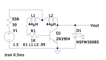
Here’s the schematic that I entered:
I determined the value of the inductors (44uH) using an online toroid calculator, specifying an FT-50-43 toroid with 10 turns through it. The K1 statement creates a transformer out of L1 and L2, with a coupling coefficient of 0.99 (just a guess, they are wound on the same toroid, I expect it to work rather well). In the circuit as presented, the battery is represented by the voltage source V1 and the resistor labelled ESR. From a data sheet for EverReady AA batteries, I found that the typical series resistance is somewhere between 150 and 300 milliohms. I picked an LED out of LTSpice’s catalog: no attempt was made to ensure it was close to the random LED I grabbed from my junkbox.
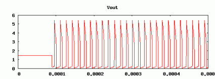
If you simulate it for a half a millisecond, and look at the voltage at Vout, you get the following graph:
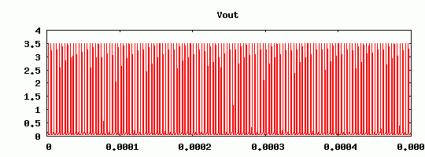
If you change the ESR to 30 ohms, and look at the voltage
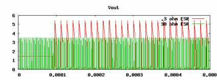
Here’s a graph comparing them:
We can see that the voltage going into the LED peaks much higher, and remains higher for a significant period longer when supplied with a battery with a lower ESR. Using the FFT function, we can determine that the fundamental frequency is around 64Kh, and we can see that the average current is around 35 ma (a bit higher than the recommended average power for the LED, but not tremendously high, given the high frequency at which it operates).
When we have a 30 ohm resistance, the average current through the LED drops to a mere 3.5ma. While the voltage does appear to peak higher than the forward voltage needed to light the LED, the current supplied is simply too short and too low to significantly light the LED.
This seems to verify my experiments to a degree. But last night, I thought of this, and thought that perhaps I could boost the ability of these coin cells by paralleling them with a capacitor. I yanked out an electrolytic of around 220uF from my junk box, and wired it in parallel with the coin cell. The LED did light, but at a very low frequency, just a couple of Hertz. If I add a similar cap to my simulation, I don’t get this behavior. Not sure what’s going on. Any real engineers in the audience care to school me onwhy what I did here is completely inaccurate/wrong/stupid?
Comments
Comment from Paul
Time 8/9/2013 at 9:32 pm
Your battery sounds too strong. I’ve heard that you’re not supposed to hook up a joule thief to a new battery, or you can burn out your led. You’re supposed to use a (barely?) dead 1.5 V battery. So your over-current sounds right to me. I just started with ltspice, so my joule thief isn’t running yet. Thanks for your schematic.


Comment from KJ6EAD
Time 5/10/2011 at 5:35 pm
In Dave Jones’ battery capacity tutorial, he talks about internal resistance quite a bit especially from 16:00-20:00.
http://www.eevblog.com/2011/01/23/eevblog-140-battery-capacity-tutorial/