Inductive Spikes: Simulation and Reality
Kindred spirits Atdiy and whisk0r over at the tymkrs blog were playing around with inductors:
They demonstrated that inductors can generative large inductive spikes: in spite of the fact that there coil is charged by a relatively low voltage, when you sharply disconnect a coil from a charging voltage, it generates a large voltage spike that can be measured (by a volt meter) and also generates a visible spark.
I thought it would be fun to see if I could simulate this using LTSpice. I wanted to make sure I understood what was going on, and try to see if I could get some measure of what voltages could actually be generated.
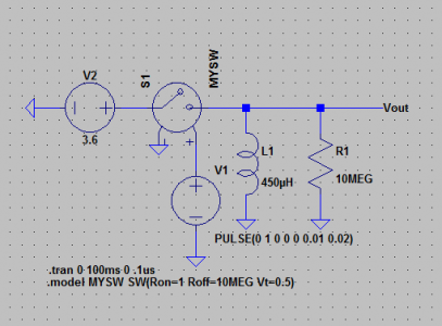
Here’s the schematic I came up with in LTSpice:
It’s a pretty simple schematic really. It’s got an inductor L1, that is about 450uH of inductance (calculated with an online calculator from rough measurements that Atdiy supplied me). The resistor in parallel is 10 megohm, which is similar to the impedance of a typical volt meter. I then have a voltage controlled switch, powered by a square wave. Whenever the input voltage goes greater than 0.5 volts, the switch connects, presenting a resistance of merely 1 ohm. When it drops below 0.5 volts, it presents a resistance of 10 megohms. The inductor is charged by a nominal 3.6 volt battery.
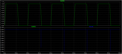
So, what does it look like when you simulate it?
Across the top, you can see the voltage that gets applied to the voltage controlled switch. Across the back, you see large negative spikes in voltage. Really large. We see spikes of nearly 7 megavolts. Pretty amazing, from a 3.6 volt supply! This simulation may be overly optimistic: after all, it doesn’t take into account the stray resistance and capacitance that are likely to be present. But clearly Atdiy’s real life test indicates that high voltages are being developed.
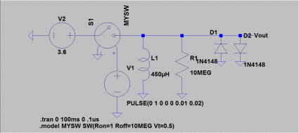
In real life applications where inductive loads might be connected and disconnected quickly to varying loads, it’s common to use diodes to protect the remaining circuit from these high voltage spikes. We can do that in our simulated circuits too. Let’s add a pair of diodes to shunt both positive and negative voltages to zero (I picked 1N4158 diodes, somewhat arbitrarily):
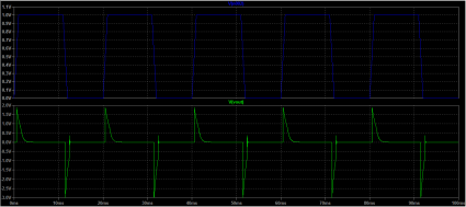
They do their job, check out the voltages:
Neat!


I recall burning three or four weeks of a sabbatical getting Saccade.com on the air with Wordpress. So much tweaking…