I recall burning three or four weeks of a sabbatical getting Saccade.com on the air with Wordpress. So much tweaking…
Question about LEDs…
A few days ago, I posted a query to twitter regarding voltage drop in LEDs:
I didn’t receive a lot of truly helpful replies: a few people reinforced the general dogma that indeed LEDs were diodes, and since they were diodes, they should have relatively constant voltage drop despite current across them. But that’s not what I am observing with my simulations using LTSpice.
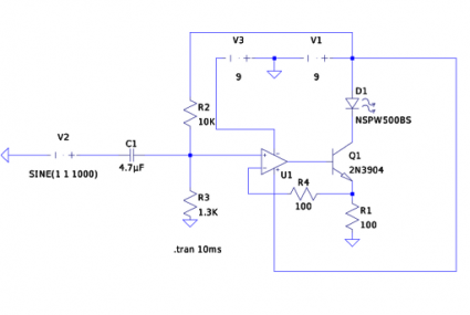
Here’s the schematic for my linear current based LED modulator more or less as I built it (for some reason the circles which define the voltage sources V1 and V3, as well as the simulated input signal V1 don’t show up, sorry ’bout that). The basic idea though is that the voltage appearing at the noninverting input of U1 is a 1V peak-to-peak audio signal, offset by 1 volt so the total range is 0 to 2V. The action of the op amp ensures that the voltage appearing at the top of R1 is the same as the noninverting input. Since the load is a constant resistance, that means the current is proportional to the voltage, and varies exactly with variations in the input voltage.
So, what are the voltage drops across the LED (D1) and the transistor (Q1)? My intuition says that the voltage drop across the LED should be (as per conventional wisdom) nearly constant. Looking at the datasheet for the NSPW500BS (a white LED manufactured by Nichia) I see that it lists a typical forward voltage of 3.6 volts (I picked it at random from the list of available LED models in LTSpice). So, what I would expect would be that the voltage drop across D1 would be nearly constant at 3.6 volts, and since the voltage drop across the load resistor mimics the input signal, that the drop across Q1 would look like 9V minus the audio voltage minus 3.6 volts.
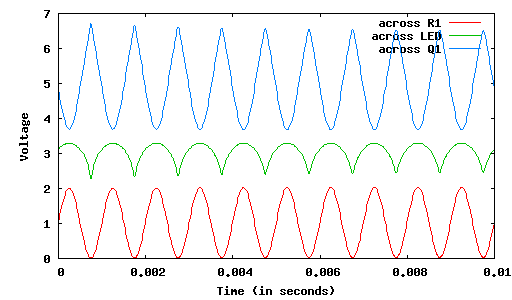
But here’s what LTSpice produces:
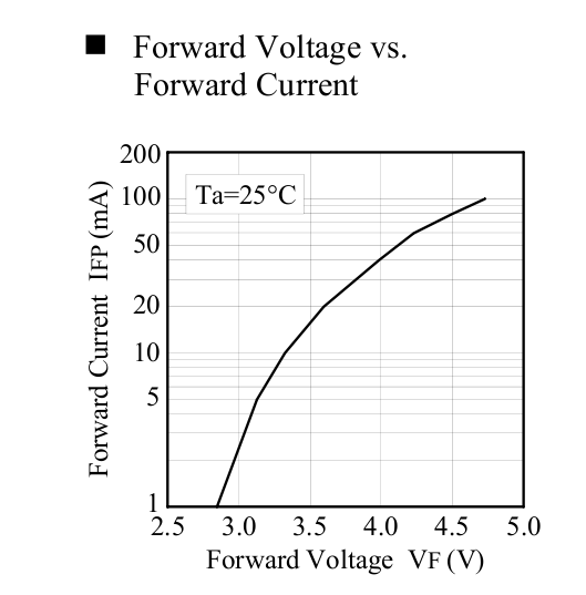
You can see that the voltage across D1 varies by nearly a volt. I tried replacing D1 with a more conventional diode (such as as a 1N4148) and the variation is much smaller (maybe 0.1V). Digging into the datasheet for the LED, I found this diagram:
Which does seem to imply that over currents of (say) one to twenty milliamps, the forward voltage drop may be a volt (and more, if you push more current through them).
So, here’s my question: is that typical of LEDs? Or maybe just white LEDs? And the more broad question: how can I translate information from the datasheet of an LED into a usable model for LTSpice so that I can realistically model this behavior?


Comment from Suraj
Time 5/23/2011 at 8:28 pm
The extra drop in voltage may be accounted by modeling the LED as a diode + resister in series.