Monthly Archives: July 2011

On the Ham Nation podcast, or the perils of perpetual promotion.

Ham Nation is a relatively new weekly podcast that is brought to us through the power of the TWIT network, Leo Laporte’s mighty podcast empire. Fellow blogger KE9V had some comments on it, some of which I agree with, and some of which I do not.

Of Dits and Bits | KE9V’s Ham Radio Blog.

First, the positives. Hosts Bob Heil and Gordon West are practically legends in the world of ham radio. Both are charming gentlemen, deeply concerned with promoting ham radio.

And in a strange sort of way, that’s what I find to be most disconcerting about the show. It tries really, really hard to convince you that ham radio is exciting and relevant. I do firmly believe it’s a great hobby. Or more precisely, it’s a bunch of great hobbies, all united under the need to get a license to operate. Some aspects of the hobby I like better than others. I can appreciate that other people might like aspects of the hobby that I do not. I can also appreciate that some people might want to promote the hobby.

But I can’t help but think that we overstep our promotion of ham radio sometimes. In trying to understand why I feel that way, I see two primary causes.

First, in our haste to bring new people into the hobby, we try to talk about ham radio in a way that the uninitiated can understand. That’s okay, but unless we are careful, we end up never talking about anything else. And frankly, I see that a lot in the first ten episodes of Ham Nation. Like KE9V, I haven’t seen that there is anything being presented in Ham Nation that anyone whose been in the hobby for more than a year will care about. In an effort to make the hobby understandable to the layman, we are stripping out everything interesting from our hobby. We are providing no inspiration to deeper achievement in ham radio. We perpetually talk about what equipment to buy, but never talk about the equipment we build. We promote simple wire antennas, without working to provide information on more complex and therefore higher performing antenna systems. And Ham Nation has this in spades. It’s not too surprising: Gordon West has made a career out of selling study aids for ham radio and getting new people into the hobby. But I can’t help but wish that there was a podcast that actually talked about ham radio in a way that at least periodically reached beyond how to solder and your first wire antenna.

Second, there is the idea that ham radio is unique among hobby in promoting virtue and intellectual development. Most hams are great people, but I believe that most people are great people. There are some really amazingly intelligent people in ham radio, but there are intelligent people in all walks of life, with all sorts of hobbies. I suspect that if your hobby was windsurfing, most of your fellow windsurfers would be good, intelligent people too. The difference is that windsurfers don’t spend a lot of time trying to convince you that windsurfers are really great people. They just accept that if you want to be a windsurfer, you’ll learn what you need to, and you’ll join a great group doing something they love. Hams want to convince you that they are a bunch of great guys, doing great stuff, but they seem to spend all their time talking about how great they are, and relatively little time showing you how great they are.

Ham Nation suffers from both of these ills.

It’s not enough to have celebrity hams. It’s not enough to tell everyone how great ham radio is and how much they will love it and how easy it is. You have to get on with doing ham radio, to demonstrate how cool you think it is, and let other people make up their own minds. When people like Kevin Rose express skepticism about the hobby, we shouldn’t tell him he is wrong: we should show him he is wrong. And we should accept that perhaps he isn’t wrong, at least for him.

It’s just a hobby after all.

On RC Filters…

Over on the #savagecircuits IRC channel on irc.afternet.org, Atdiy was trying to decipher the mysteries of a mainstay of analog circuit design: the RC filter such as the one pictured on the right (diagram cribbed from Wikipedia) It dawned on me that (newbie as I am) I didn’t really have a clear understanding of them either, so I thought it would be worth the exercise to go through the mathematics of them as well, and try to derive the simple formulas from (more or less) first principles.

First of all, it’s interesting to just try to understand what happens at DC voltages. No current flows through the capacitor at DC, so the output voltage is just the input voltage (when measured as an open circuit, more on this later). If you are a total newbie like me, you can look at the capacitor symbol, and note that one side is not connected to the other (it’s an open circuit), so no current can flow across it (at least, at DC) frequencies. But at higher frequencies, we need to consider the behavior of the capacitor, which means that we need to consider impedance.

If you don’t grok complex numbers, the road ahead will be a tiny bit bumpy. I didn’t have enough brain power to write an intro to complex arithmetic, but if it’s new to you, consider reading up on it. For now, just remember that complex numbers can be manipulated like regular numbers (adding, multiplying,dividing and the like) but have different rules.

Rather than derive anything at this point, we’ll just cheat a tiny bit and introduce a formula to find the reactance of the capacitor. (You should not feel too uneasy at this point by introducing what seems like magic at this point. The following equation just describes how capacitors work. You probably accepted that resistors could be described by a single number (expressed in ohms). Because capacitors have more complicated behavior in AC circuits, they need a bit more complicated description, but not too much).

The capacitive reactance of the capacitor is given by:

[latex]X_C = \frac{1}{2 \pi f C}[/latex]

where [latex]f[/latex] is the frequency of operation, and [latex]C[/latex] is the capacitance in farads (be careful, not microfarads). For instance, a 1 nanofarad capacitor has a reactance of about 160 Ohms at 1Mhz.

I glossed over something a bit there. The reactance we computed is measured in ohms, which makes it seem like it’s a resistance. But in reality, it’s an impedance (usually written as the symbol [latex]Z[/latex]). Impedance is a measure of the opposition of a circuit to current, but it generalizes resistance by taking into account the frequency dependent behavior of capacitors and inductors. In particular, impedance varies with frequency.

You can split the impedance into the sum of two parts, the pure resistance (usually written as [latex]R[/latex]) and the reactance (usually written as [latex]X[/latex], as we did above when we were computing the reactance of the capacitor). The total reactance of a circuit is the inductive reactance minus the capacitive reactance. If the overall reactance is negative, the circuit looks like a capacitor. If the sum is positive, it looks like an inductor. If they precisely cancel, then the reactance disappears, and the circuit presents no opposition to current at all.

But how do we handle resistance? Here’s where the complex numbers come in.

[latex]Z = \sqrt{R^2 + X^2}[/latex]

[latex]X = X_L – X_C[/latex]

The nifty bit is that you can treat impedances exactly as if they were resistances (e.g. we can use Ohm’s law) just so long as we remember that we are dealing with complex quantities. I decided to write a small Python program which could be used to compute the filter responses of RC filters:

[sourcecode lang=”python”]
#!/usr/bin/env python
#
# Here is a program that works out how RC filters
# work. Here is a diagram of the prototypical
# RC low pass filter, sampled across a resistive
# load Rload.
#
# R
# Vin -> —/\/\/\/\—-+——–+ Vout
# | |
# | /
# | \
# C —– / Rload
# —– \
# | /
# | \
# | |
# —– —–
# — —
# – –

import math
import cmath

RLoad = 1e9
R = 600 #
C = 0.0000001 # .1uF

for f in range(10, 100000, 10):
XC = complex(0., -1/(2.0*math.pi*f*C))
Z = cmath.sqrt(XC*XC)
t = RLoad * Z / (RLoad + Z)
Vout = t / (R + t)
print f, 20.0 * math.log10(cmath.sqrt(Vout*Vout.conjugate()).real)
[/sourcecode]

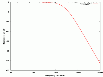
If you take the data that gets printed out here and graph it, you get the following:

I built the same circuit in LTSpice just to check my understanding, and the graph appears identical. If you search through the data to find the place where the response drops to -3db, you find it occurs around 2650 Hz. The traditional formula for filter bandwidth is

[latex]F = \frac{1}{2 \pi R C}[/latex]

which when you plug in the values I chose, you end up with 2653.9 (which is pretty good agreement).

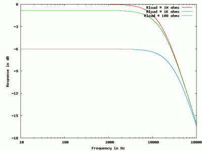
Addendum: This filter works best when the input impedance is very low (compared to the 600 ohms that we chose for the input resistor [latex]R[/latex]) and where the load impedance [latex]Rload[/latex] (here purely resistive, but it could also be complex) is high. If the load were low (Rload was comparable or less than than R) then the losses would be higher. (Ignore the capacitor. If Rload is small compared to R, then the voltage, even at DC, is already divided down to a lower value, this shifts the entire curve downward).

Addendum2: I wrote this hastily. If it doesn’t make sense, or people have suggestions, don’t hesitate to add them in the comments below.

Addendum3: Atdiy asked me to run some simulations showing how the load [latex]Rload[/latex] changes the output to demonstrate loss. Here, I kept [latex]R = 100[/latex], but varied [latex]Rload[/latex] from 1M ohms, to 1Kohms, and then down to just 100ohms. You can see the entire curve moves down, with only 100 ohms of load resistance, the voltage is -6db (multiplied by 0.25) even at DC).

Addendum4: Atidy has started her series on filter design, which includes a qualitative description of how these filters work that you might find easier to understand. Check it out here.
.

PDP-10/X on an FPGA

I think I saw this a couple of years ago, but Doug Conroy seems to have made some progress on his implementation of a PDP-10 on an FPGA. It now can apparently boot ITS. I’m more interested in the prospect of running TOPS-10 so I can relive my early days, but booting ITS is pretty awesome. Bookmarked for later retro-geek-hacking-envy:

PDP-10/X.

Hackaday Comment Policy: We’re cleaning up

I am a long time reader of Hack A Day. It’s a great website, and often details projects that I find interesting well before they are picked up on other sites. It also tends to drive significant amounts of traffic to sites mentioned, so it’s good publicity for many interesting objects.

But lately, their comment section has become a complete and utter cesspool. I’ve read hundreds of comments over the last few months which fall into predictable categories…

  • You’re stupid.
  • Your project is stupid.
  • Why didn’t you do X?
  • That isn’t a hack.
  • Your grammar/spelling is wrong.
  • That video is fake, nobody could do X.
  • Any of a number of racist, sexist, and idiotic comments which decorum prevents me from reproducing.

I don’t see any of these kinds of comments as helpful, useful, informative, or inspiring.

To their credit, it appears that the Hack A Day crew are beginning to realize that this kind of stuff does nothing to enhance their brand and are taking steps to correct this.

Hackaday Comment Policy; We’re cleaning up. – Hack a Day

My own blog policy is simple (and given the relatively low number of non-spam comments, pretty easy to implement): be nice. If your postings aren’t nice, then they aren’t going to stay. I can handle disagreements and dissent, but if you can’t do it in a civil way, you can post your comments on your own blog and link back to me. I won’t mind. My blog is like my virtual living room. I wouldn’t allow anyone to come in and act like a complete buffoon in my house, and I’m not going to pay for the web services that lets them do so in my virtual living room either.

And arguing that some kind of “free speech” should be the rule is not going to fly either. You are entitled to your own free speech, but I don’t have to pay for it or promote it. You are free to pursue your own free speech using your own resources, but you don’t get to volunteer mine.

Some people have asked that come kind of comment voting system (like that employed on Slashdot) could be employed. I’ll merely say that I don’t read Slashdot anymore precisely because gaming of their comment system has reduced its utility considerably. It’s never been clear to me that such systems can be engineered to even reduce, much less eliminate, the kinds of negative comment trolling that I’ve been seeing.

Here’s my advice: if you think that a particular project on Hack A Day (or brainwagon or any other site) is deficient in some way, then get off your duff, make a better project, and publish it. Lend your own expertise to the discussion, and help elevate everyone’s game. That’s what the web should be about.

Oh, and keep up the good work, Hack A Day.

How to mistake correlation and causality, from Scientific American

My tweets this morning included a link to a story by Scientific American editor Anna Kuchment, entitled “How to raise a science fair champ”.

How to raise a science fair champ | Scientific American Blog Network

On the one hand, it’s a mildly interesting look at some talented kids who have risen to the top of the increasingly prestigious world of science fairs. But the thing that struck me was how it totally failed to deliver on the promise of the title. The story repeatedly mistakes correlation with causality.

Here’s the basic problem: Kuchment is looking at 15 finalists for the first Google science fair, and trying to determine what they have in common, and then implies that if you can do the same thing with your children, they could join the same kind of elite company as these 15. But that’s a serious mistake, and an incredibly persistent one.

Take for instance this:

Leaving stats aside, the top things finalists named as the foundation of their interest in science was having a family member who was interested in science and making trips to the local science museum.

That seems like an interesting fact, but it is actually not a fact, but just a story. There are plenty of people who aren’t science fair champs (or even interested in science at all) whose family members are interested in science and who take them to science museums. Kuchment is reasoning from the result back to the cause. If one is to actually learn something about what makes science fair champs, one needs to look not just at champions, but all the non-champions as well. And when you do that, I suspect that you’ll find thousands of candidates who have many or all of the distinguishing characteristics of the golden fifteen that Kuchment interviewed, save that they didn’t win science fairs.

As human beings, we are all interested in achievement. Mark Zuckerberg becomes Time Magazine’s Man of the Year because he was the brains behind Facebook. We idolize Steve Jobs because of the meteoric rise of Apple over the last decade. We like to read the stories of the rich and famous, because we hope that if we can just do what they did, that we could attain some small portion of the success that they have. But it is devilishly difficult to learn anything truly useful from the stories of the few, because we naturally don’t hear the stories of the many who did all the same things, but didn’t end up rich and famous.

No doubt that a lot of my current sensitivity to this kind of thinking is coming from the fact I’m currently reading Duncan Watt’s Everything is Obvious: *Once You Know the Answer. It’s an excellent book, and tries to shake our confidence in the common-sense reasoning that we all seem to rely on when we look at the world around us.

Dave Richards, AA7EE constructs The WBR by N1BYT

Thanks to Bill at the SolderSmoke blog for posting a link to Dave Richards’ construction project. He made a slick version of the Wheatstone Bridge Receiver, a regenerative variant created by N1BYT and published in More QRP Power. I’ve looked at this receiver before, and found the design to be pretty interesting, but Dave goes above and beyond by showing all the things my projects lack in great abundance: like neatness, care, and planning. Check it out:

The WBR – A Simple High Performance Regen Receiver for 40M by N1BYT « Dave Richards AA7EE.

The Kansas City Standard

I was pondering my laser transmitter the other day, and began to think of how I might transmit digital information from the Arduino to the remote receiver. Since I am old, I remember the old days where programs used to be stored on an obsolete audio storage medium called cassette tape. Indeed, the first storage device I ever used was the Atari 410 tape drive pictured on the right.

The Atari stored data at 600 baud, using FSK (data is stored as short bursts of two different tones, in the case of the Atari 3995 and 5327 hz), using a variant of the so-called Kansas City Standard. KCS was a standard for storing data on cassettes that was developed at a Byte magazine sponsored symposium in 1975.

Data is converted to short bursts of 1200Hz and 2400hz tones to represent zeroes and ones, respectively. Each burst is 1/300 of a second long, meaning that it sends 300 bits per second. Each 8 bit character is framed by a 0 start bit, and a pair of 1 stop bits so that character frames can be identified. It was designed to be a reliable if slow format, and succeeded on both counts. It transmits about 27 characters per second. An 8K download would take about five minutes.

It’s amazing we ever lived through the stone age.

Anyway, I thought it would be fun to make an Arduino library to send this information over my laser link, but first I decided that it would be good to test to make sure I understood how the format worked. So, I coded up a small program to generate some test .WAV files from an input data file. I made the problem simpler by generating the output at the somewhat non-standard sample rate of 9600 samples per second. This considerably simplifies the generation of samples, since they only would have amplitudes of zero, plus or minus one, and plus or minus sqrt(2)/2. I coded up the following C code, and generated this WAV file.

A WAV file that contains an ASCII test message, encoded in Kansas City Standard

The encoder is simple, the decoder, somewhat less so. So, to test that I was generating the proper bits, I used Martin Ward’s decoder written in Perl which did a good job of decoding the sample WAV files. I haven’t tested the robustness of this format with respect to noise yet, but it does appear to work reasonably well.

It wouldn’t be that hard to modify the simple sound generation code I used before to send data in this format. I think I will try to get to that next week.

[sourcecode lang=”c”]
#include <stdio.h>
#include <stdlib.h>
#include <math.h>
#include <sndfile.h>

/*
* kc.c
* A program which takes a file as input, and encodes it via the old
* Kansas City Standard – a 300 baud format that was used by old
* microcomputers to store data onto cassette tape.
*
* http://en.wikipedia.org/wiki/Kansas_City_standard
*
* We are going to produce a 9600 sample per second output file…
*
* Each "baud" is 32 samples long.
*
* A ‘0’ is 4 cycles @ 1200 Hz.
* A ‘1’ is 8 cycles @ 2400 Hz.
*
* 0 – 0 R2 1 R2 0 -R2 -1 -R2
* 1 – 0 1 0 -1
*
*/

#define R2 (.70710678118654752440f)

SNDFILE *sf ;
SF_INFO sfinfo ;

void
output(float f)
{
sf_write_float(sf, &f, 1) ;
}

void
send(int bit)
{
int c ;

switch (bit) {
case 0:
for (c=0; c<4; c++) {
output(0.f) ;
output(R2) ;
output(1.f) ;
output(R2) ;
output(0.f) ;
output(-R2) ;
output(-1.f) ;
output(-R2) ;
}
break ;
case 1:
for (c=0; c<8; c++) {
output(0.f) ;
output(1.f) ;
output(0.f) ;
output(-1.f) ;
}
break ;
default:
abort() ;
}
}

void
encode(int ch)
{
int i ;
send(0) ; /* start bit… */
for (i=0; i<8; i++) {
send(ch & 1) ;
ch = ch >> 1 ;
}
send(1) ; /* two stop bits */
send(1) ;
}

main()
{
int i, ch ;

sfinfo.channels = 1 ;
sfinfo.samplerate = 9600 ;
sfinfo.format = SF_FORMAT_WAV | SF_FORMAT_PCM_16 ;

sf = sf_open("test.wav", SFM_WRITE, &sfinfo) ;

for (i=0; i<9600/4; i++)
output(0.) ;
while ((ch = getchar()) != EOF)
encode(ch) ;
for (i=0; i<9600/4; i++)
output(0.) ;

sf_close(sf) ;
}
[/sourcecode]

Nine years of blogging…

Glancing to the side bar, it appears that today in 2002 was the first post on my blog.

This should be post number 3,690. I’ve had 2,286 comments. I’ve used 110 category tags. Over the 12 months, Akismet has removed 193,915 spam comments, and there have been 798 pieces of “ham”. The peak month for spam was November, 2010, where I received 35,764. As the result of that pain, I installed a RECAPTCHA plugin, and spam levels decreased to around eight thousand pieces per month.

Those are the statistics.

So, what’s the state of brainwagon? I’m posting somewhat less than in past years, but usually with less recycled links. When I do post links to the blog, I’ve been better at adding some value by presenting links to similar projects or other information that might prove interesting. I’ve begun to try to do more of my own original projects, and trying to use YouTube video more effectively. I’m also using Twitter more effectively. I’m meeting more people online, and trying to engage more completely.

Overall, I think brainwagon is going rather well. At times, it seems like shouting in a dark, empty room, but there are at least signs that some of my neighbors are listening.

Happy birthday, BrainWagon.

Addendum: The WP Post Words plugin allowed me to count the words written in all my posts:

Hallway Test of the Arduino PWM Laser Transmitter

The other day, I showed how the Arduino could be used to generate PWM audio and send it over a very short distance using an LED. In my ever increasing pile of parts, I had some small 5mw red laser diode modules. These modules are supposed to be driven by direct connection to three 1.5 volt batteries, and draw a maximum of 50ma or so. In a fit of “what the heck”, I just soldered some better clip leads to one of them, and hooked it (without any other current limiting) to the PWM output of the Arduino. I measured the current draw as being about 13.7ma, which seemed fine, and the laser didn’t explode. So, the next day, I brought it into work and tested it out in a long hallway:


(Forgive the somewhat lower quality video, I sent them from my iPhone, and the quality leaves much to be desired). But it obviously works extremely well: the signal is easily discernable at even low settings of the amp.

AE6TY on Software Defined Radio

This morning I realized that somehow I had failed to listen to the latest SolderSmoke episode (#135), so during my somewhat longer than usual commute (traffic) I set it going and had a listen. And wow, some really great stuff, especially the report by Bob Crane, W8SX on the Four Days in May (FDIM) QRP conference last month. One thing that caught my attention was a presentation by Ward Harriman, AE6TY, on “Software Defined Radio Without the Math”. Since that is a topic I’ve always been interested in, when I got to work, I looked up his website, and found that it’s a great treasure trove of information. Like Jeri Ellsworth’s recent project, Ward has designed an SDR which doesn’t require a PC to work, but instead of using an FPGA like Jeri, he chose to use a dsPIC processor. He’s also got the schematic and PCB files online, and the whole build is documented in a series of articles for QRP Quarterly that you can download from his website. Awesome stuff! Check it out.

AE6TY on Software Defined Radio!.

Parents can trump mentors…

Back on July 8th, I wrote a brief post about mentoring. Hopefully, some of you read it. In case you didn’t, I made the completely unsupported claim that mentors don’t normally create interest, they merely nurture the interests that are already there. They also serve to help remove the obstacles that frustrate the enthusiasm of newcomers, providing material, advise, or inspiration.

Gee, that sounds like a parent, doesn’t it?

Last week, I had the opportunity to think about this topic a lot. On Wednesday, I got to tell this
story, which I’ll go ahead and tell you now.

When I was sixteen or so, I can remember being in my grandmother’s dining room, excitedly explaining something about my (then new) Atari computer to her. Remember: this was 1981 or so, and I think it was moderately safe to say that grandmothers as a demographic were fairly ignorant of microprocessors. But my enthusiasm was bubbling over, and she patiently listened to me until I was forced to take a breath and wandered away.

She wandered back into the kitchen, and had the following conversation with my Mom:

Grandma: “Boy, Mark sure seems to know a lot about computers, huh?”
Mom: “Yeah, he’s pretty smart.”
Grandma: “I haven’t the faintest idea what he’s talking about.”
Mom: “Yeah, me neither.”
Grandma: “He doesn’t seem to mind though.”
Mom: “Nope, just keep nodding and smiling. He doesn’t care if you understand, he just wants you to listen.

I used to believe that this story was about my grandmother. She was, after all, a remarkable woman. She taught me a lot: how to cook, how to crochet. Most of the money I spent on that first computer came from mowing her lawns. She made me lemonade on hot days. She would make pies and cobblers from the blackberries and huckleberries I’d pick. When I got my driver’s license, I would drive her on errands. Sadly, when college came, I saw quite a bit less of her. Her breast cancer reasserted itself, and she passed away about 26 years ago. I still miss her, and think of her when I make pickles, potato salad, or pork shoulder.

But I didn’t realize until last week that this story was also about my mom. She too, was a remarkable woman. After all, in 1980, she was willing to support the insane desire of a sixteen year old boy to learn about computers. She didn’t have any expertise, but she patiently accepted that what I wanted to learn about good for me, and she did all she could to help remove the barriers that might have stymied my initial interest. That early interest blossomed into a rewarding career and remains the core of the intellectual joys that you get a glimpse of through my blog. And of course, she was my mom, and loved me (and the rest of her children) with the kind of love that only a mother can.

On Friday July 8th, I received a phone call that my Mom had passed away. I got to tell the story I just related to you at her funeral to her friends and family.

In the grand scheme of things, expertise isn’t that important. Knowledge isn’t that important. My mother and grandmother didn’t have any expertise or special insight into what I was doing. What they did have was love, and that love gave them faith that the path that I saw for myself (even at age 16) was worth supporting and aiding. They removed obstacles. They loved me for who I was and what I wanted to do, unconditionally.

I cannot begin to express the degree to which she will be missed.

Addendum: You might have asked where Dad was in all of this. Dad was awesome too. At age ten or so, I got it into my head that I wanted to build a telescope. I had read some book that said you could do it. Without any real expertise, he supported the project. We sent off to Edmund Scientific and got a mirror grinding kit to make a 6” mirror. We dutifully ground and polished it. But in the midst of that project, he developed Hodgkin’s lymphoma, which eventually claimed his life in 1978, and I never got to finishing the mirror or putting it into a telescope. Years later, I moved to California, and discovered the Telescope Maker’s Workshop at the Chabot Science Center in Oakland. I got it into my head that I would like to finish the telescope I had started all those years ago. My mom still had it tucked away in her closet. With help from the workshop, I finished that mirror (and went on to help many others do the same as a volunteer instructor) and finished the scope (mostly, it could still use some paint) with the help of my brother. I still have the scope, and will never sell it.

This week, I do feel sad for my loss, but there is no need for pity. All three of the people I’ve lost have left my life full of joy. If I could do the same, I’d consider my own life “well lived”.

Using the Arduino to send audio via pulse width modulation

I’m still interested in doing light based communication, but I haven’t made a lot of progress. I did build an LTSpice model of the circuit I used yesterday, but other than verifying that it probably would work as built (which it did) I didn’t feel like I had enough brain cells working to optimize the circuit. So, instead, I decided to try to see if I could use an Arduino to send reasonably high quality audio over light using pulse width modulation.

It doesn’t really seem all that hard in principle: the Arduino libraries include an analogWrite() command which can be used to generate a PWM signal on an output pin. But the problem is the frequency of operation is quite low: around 500Hz or so. Since I was interested in sending voice bandwidth signals (say sampled at 8000Hz or so) the PWM “carrier” frequency simply wasn’t high enough.

So, I did a bit of digging. It turns out that you can configure the timers on the ATMEGA328 on board the Arduino pretty easily, and if you dig through the datasheet, scratch your head a bit, and then type carefully, you can come up with the right incantation. Which I did: in fact, it worked the very first time I downloaded it to the board.

I recorded a second or so of audio using Audacity, dumped it as an 8 bit raw audio file, and then converted it to bytes. I then created a very simple program which simply copies each byte to the PWM overflow register, and then delays for 125 microseconds (1/8000 of a second). Other than that, just some simple bit twiddling to change the PWM prescaler to operate at the full 16Mhz clockrate, and… voila.

Witness the video:


Here’s the core of the code (the actual audio data has been stripped for brevity):

[sourcecode lang=”c”]
#include <avr/pgmspace.h>

prog_uchar bwdat[] PROGMEM = {
0x80, 0x80, 0x80, 0x7f, 0x80, 0x80, 0x80, 0x81, 0x80, 0x80, 0x80, 0x80,
// … lots of lines deleted for brevity…
0x80, 0x80, 0x80, 0x80, 0x80, 0x81, 0x80, 0x7f, 0x7f, 0x80, 0x80, 0x80,
0x80, 0x81, 0x81, 0x80, 0x80, 0x81
} ;

void
setup()
{
pinMode(11, OUTPUT);
TCCR2A = _BV(COM2A1) | _BV(WGM21) | _BV(WGM20);
TCCR2B = _BV(CS20) ;
OCR2A = 180;
}

void
loop()
{
int i ;
char ch ;

for (i=0; i<sizeof(bwdat); i++) {
ch = pgm_read_byte_near(bwdat+i) ;
OCR2A = ch ;
delayMicroseconds(125) ;
}
}
[/sourcecode]

Laser audio transmitter…

Okay, so last night, after just testing one of the laser modules I had, I decided to try to make a transmitter to send audio over laser light to my “solar cell + Radio Shack amplified speaker” receiver that I was experimenting with earlier. I suppose I could have used my linear current LED modulator, but there were reasons to believe that it wouldn’t work all that well. Lasers are inherently nonlinear: they are meant to operate under reasonably narrow ranges of drive current, whereas LEDs are fairly linear over a wide range of drive currents. Thus, linear current drive isn’t appropriate for lasers. It would be much better to use pulse-width modulation to simulate AM modulation on a higher frequency carrier.

So, that’s what I did.

I took the quickest way out: I built one using a 555 timer. I had previously built a simple AM radio transmitter using a 555 timer, and somewhat unsurprisingly, the exact same circuit can be used to drive a laser. You simply hook a current limiting resistor (150 ohms in my case) and the laser diode to the output at pin 3 of the 555 astable multivibrator, aim it at your solar cell receiver, and.. voila! It works!

Well, it sort of works. The sound quality, like the sound quality of the AM transmitter that I liked to above, leaves something to be desired. It’s not unintelligible or anything, it’s just not particularly high fidelity. So, rather than shoot a video that demonstrates it, I thought I’d spend some time trying to figure out how to design a system that would work better. Here are some of my basic thoughts:

My input biasing and scaling for the prototype was completely adhoc. I merely injected the voltage directly onto pin 5, without any impedance matching, scaling or biasing. That’s mostly because I was pretty sure that even without those things, I’d get some modulation that would be detectable. I was right, but I really should go back and figure out what the right answer is to ensure that I have deep modulation with a typical -1v to 1v, low impedance audio signal (which is what I’m feeding into it).

The AM carrier frequency I picked was selected by just using two resistors (I think 1K) from my junkbox, and then selecting caps to get the frequency of oscillation above the audio frequencies people can hear. I think I ended up with a 0.01 uF cap, which results in a frequency of oscillation of around 46Khz). That seems okay, but on the receive side, we could benefit by some bandpass filters centered around that frequency (this would hopefully decrease the 60 hz buzz I get from flourescent lighting).

I got a few more ideas, but they will have to wait until after breakfast. Oh, and baseball. A double header, A’s versus Angels.

Addendum: Okay, before I left, I recorded a quick demonstration to show how it works. It’s not bad actually:

Just playing with laser diodes…

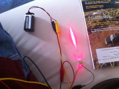
A while ago, I got some laser diodes from from dealextreme.com. They were dirt cheap, but I haven’t had any chance to hook them up. I didn’t have a datasheet for them either, so wasn’t sure exactly what I should do to current limit them. So, I hooked it in series with a 150 ohm resistor and a 9v battery, and measured both the current and the voltage drop across the laser module. The resulting beam seemed bright and steady.

The current through the circuit was approximately 37ma, and showed a voltage drop of almost exactly 2.5 volts. That means the total power consumed is about 92 mw. These laser modules seem to be good quality: the beam is bright and quite round. While I don’t have a specific model number on these diodes, staring at datasheets for similar diodes make me believe I’m probably not too far off in terms of picking a good current.

Yes, yes, I should use a better constant current circuit. This was just a first test.