I recall burning three or four weeks of a sabbatical getting Saccade.com on the air with Wordpress. So much tweaking…
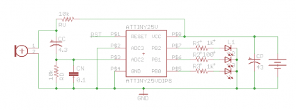
Schematic for tanjent’s “bliplace”
Yesterday, I wrote about soldering together my bliplace kit. Today, I thought I’d have a peek at the code and the schematic. Here’s the schematic:
Not much there, but a couple of interesting things. The microphone is an electret, which needs some power to be functional (supplied through the 10K RU resistor). To me, the capacitor CC and the RD resistor look like a high pass filter, with the supplied values the cutoff frequency is nominally about 160Hz. Not 100% sure I understand how the capacitor CN or what the overall input impedance is for the ADC input pins on the Atmel chip, so I am not 100% sure I understand the subtlety.
I also thought that current limiting resistors were interesting. The center LED always seems to glow brighter, and this seems to be because R2 is only 100 ohms, compared to the 1000 ohms that were used for the other two. I also wondered about the LEDs: this gadget is powered by a single 3V cell. The ATTiny25/V can run down to 1.8 volts, but I thought that white LEDs had fairly high forward voltage requirements. For instance, this page on Wikipedia says that the typical voltage drop for white LEDs is around 3.5 volts. I don’t have a lot of white LEDs lying around, but it does suggest some experimentation.

Comment from Kevin
Time 8/5/2011 at 2:21 am
http://www.atmel.com/dyn/resources/prod_documents/doc2586.pdf
This is based on the ATTiny. With a couple K of flash, this thing is capable of doing a lot more than blinking lights. I was thinking that if you added a MOSFET to the output stage that it would probably be able to drive cold cathode lights. Of course, not with the coin cell it uses for power.
With a few AA batteries, you could be lit like Elvis 😉