Monthly Archives: December 2011

K6HX QRSS Beacon ON AIR…

Well, this morning I did a bit more work on my G0UPL beacon kit. As I mentioned yesterday, I got was having difficulty with the frequency swing: despite a very tightly wound gimmick, I was getting just a little over 1Hz or frequency shift. Late last night I decided to just try a new one: there obviously had to be a fault there. Sure enough, I wound a new one, installed it, and was suddenly getting 30Hz of frequency shift! Feast or famine, isn’t that the way of it? I trimmed it down, and unwound it a bit, and now am getting a nice, reasonable 4Hz or so swing, which is clearly visible in Argo, but also narrow enough to be tidy.

I had also noticed during testing that the QRSS beacon controller was powering up in 15s/dit mode, which is a tad too slow even for the patient. I then decided to take notice of the “Important Notice” on Hans’ documentation, and grounded pins five and six with a small jumper on the bottom of the board. It now powers up reliably in six second per dit mode.

I then decided to try to measure the output power. And… on the antenna terminals, I was measuring, well, nothing! That’s not good. I then backtracked to the 2N7000 FET, and found that there was indeed a signal on the Gate, and it was modulating (although the waveform looked pretty wonky). Probing various places along the filter chain quickly discovered the bad solder joint, and I had power.

I then tried to do some adjustment of the output power. I wired up a 2W 47 ohm resistor as a dummy load, and hooked up my scope. I found that if I peaked the output power with just under six volts peak-to-peak (a little less than 100mw) the 2N7000 got fairly toasty hot. I backed off the power to just 4 volts peak to peak (around 40mw) and the transistor seems fairly calm. I thought I should be able to do a bit better, but 40mw isn’t all that bad, so… I decided to get it on the air.

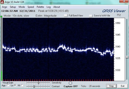
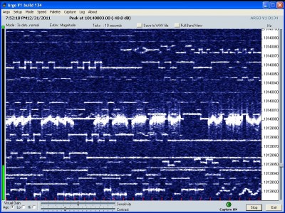
And here it is, appearing on KK7CC’s grabber (click to get it live), right around 10.140040 Mhz:

It works! KK7CC is in Las Vegas, which is around 560 miles from my location. Not bad for 40mw output power.

I’ll leave this up for a while, I’m interested in getting reception reports and screen grabs at my ARRL mailbox. I will eventually take it down, get it mounted inside a nice little Altoids box, and perhaps figure out why the output power is well short of the 100mw that I should be able to pull out of it.

In the mean time, I hope everyone has a safe and happy New Year’s Eve!
QRSS Beacon assembled, but not quite right…

I ordered myself one of Hans Summers’ QRSS beacon kits before Christmas, and it arrived a few days ago. Yesterday, I started tinkering it together, and today got it hooked up and began testing.

First, the good news:

  1. The oscillator is running.
  2. I was able to adjust it with the trimmer to get it into the MEPT portion of the 30m band.
  3. The AVR is alive and running.
  4. Tone output works, and it is detecting the 6s per dit QRSS mode properly.

But… all is not well. Here’s an example output recorded with Argo on my FT-817 placed adjacent, without any antenna at all. The QRSS beacon is transmitting into a 1W 47 ohm resistor that serves as a dummy load.

As you can see, the output is a bit wavy, and looks a bit unclean as well, with lots of spurs. But the primary thing is the deviation is only about 1.5 Hz (I recorded this in 10 second dit mode on Argo). I tried adding some additional twists to the gimmick cap, but that didn’t seem to help much.

I suspect the general poor quality of the output may be because I’m using a 5v power supply of unknown quality (perhaps some additional filter caps across the power leads may be helpful?). I’ll probably try to make a longer gimmick tomorrow. I also am going to get it hooked up to the scope to adjust the power properly as well. It’s also not in a box yet, and my dining room table is a bit drafty, so thermal drift is a distinct possibility.

Anyone else have any ideas on how to tame the ragged castle walls?

Addendum: I couldn’t let it sit: it’s one o’clock in the morning and I decided to make a new gimmick and try it out. And, of course, it worked a lot better, giving about 30Hz of swing! Ouch. I trimmed the length down, and unwound it a bit more, and now it’s down to a more respectable 8 or 9 Hz. I’ll probably unwind it a bit more when I get it in the case and setup for final operation.

But here’s an odd thing: I jumpered it for 6 second dits by jumpering the 2-5 connection at the top of the AVR, but it’s acting as if is set to 15s dits. Do I need to ground pins 5 and 6 as well? Perhaps they are floating?

Addendum2: I suppose I should have read the Important note on this page.

Nanode on the Web!

Well, to test my nanode‘s Ethernet capability, I put it on the web! Check it out by clicking this link. Hurrah! Not too impressive, but consider: it is dynamically generated on an eight bit microcontroller that costs about $35, Ethernet included. Perhaps not as cool as the Raspberry Pi, but unlike the Raspberry Pi, you can get a nanode.

But all is not well in the nanode/Ethernet universe either. There appears to be a veritable Pandora’s box of different libraries for Ethernet on the Arduino. This appears to have happened in part because the “official” Ethernet shield is based upon Wiznet W5100, while the nanode (and other inexpensive shields) appear to be based upon the Microchip ENC28J60. I can understand that to a certain degree (the Microchip part is less than $4 in unit quantities from Digikey, and is available in a through-hole PDIP package) but there appears to have been a bit of fragmentation of development even within the ENC28J60 code development. The nanode folks appear to be working with Jeelabs, so I used their EtherCard library which was available via git, and that seems to work pretty well (no changes, worked straight out of the box). The TCP/IP implementation limits HTTP responses to a single packet, so pages have to be small, but is probably sufficient to web-enable a great deal.

I was wondering: is there a more capable implementation that implements multiple packet responses? It seems like it would be helpful for many applications. Any experienced Arduino/Ethernet programmers can respond below. Does the official Ethernet shield provide that capability?

Christmas Kit: The Nanode

My wife is the best. She listens to me even when I yammer on about the most boring and geeky of topics, and does so with patience and grace. What’s more, she even remembers what I talk about, and I reap the benefits at Christmas time. I mentioned Nanode about a month back, because I thought it was cool: it’s an Arduino compatible kit that sells for about $35. “That’s not so good”, think you. But the cool thing is that it includes Ethernet. It also has a couple of other improvements. It has a double row of pin headers. The inner set are compatible with the (incredibly annoying) irregular Arduino shield spacing, while the outer set are on standard 0.1″ headers which allows you to solder in pins and use it easily on a breadboard. It also includes a space to solder an external SPI memory (SRAM, FRAM, or EEPROM) for additional expansion. Nifty.

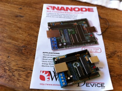
Here is my assembled (and functional) nanode:

The instructions say 1.5 hours, it took me a little over two, because I went very slowly and methodically. It’s not difficult, but it’s a fair amount of soldering, and it’s easier to make sure that you do a good job as you go along, rather than spend it debugging later. There were only a couple of minor problems with the instructions: the 22pf ceramic caps shown in the pictorial are actually blue caps in my kit, and the what the instructions showed as blue were in fact little yellow caps. The later required a bit of lead manipulation to get them to fit tidily (their natural spacing was a bit wider than what the PCB has). I didn’t see where they specified to insert the LED’s current limiting 270 ohm resistor, but it was obvious to me at the end where it went. Getting the Ethernet socket in place took a little careful manipulation of the pins. But in the end, it all worked out okay, and when I powered it up, the LED blinked to indicate all was well. I moved my Tiny BASIC interpreter over, and after fixing a minor bug that I introduced the day before but didn’t catch, had it running basic programs to blink LEDS. Huzzah!

It seems like a good kit, really. But there are a few things I thought were odd. The place to solder the SOIC memory expansion is on the bottom. And, in spite of the fact the rest of the kit is entirely through hole, this one is surface mount. That’s not a big deal, but there is something that kind of bugs me: it requires other board modifications to make it work for most of the memory chips I’ve looked at. The problem is that there aren’t any level converters wired to it. The board itself is mixed voltage: 5v for the ATmega328, and 3.3v for the Microchip Ethernet, but this isn’t carried over to the memory expansion. To really make this work, you need to convert the board to run on 3.3V, and that requires hardware mods (replacing the regulators). And frankly, I wish they had. Yes, I understand that some shields need 5v, but the precedent of 3.3v Arduino Pro boards has already been set, and I suspect that much of the complexity of the existing board is in the resistive dividers that it needs. As it is, I think it will actually be simpler to do memory expansion via a small data board that rides on the headers, and includes the necessary level conversion. It also means I can use the PDIP version of the 23K256 chip, which is more breadboard friendly.

I was also surprised that they didn’t include an SD card slot. If you have an Ethernet, one of obvious ideas is to serve webpages, and you need some space to store them. The obvious thing would be a small SD card. I recognize that the board space is at a premium (especially since this kit uses through hole packages for ease of assembly), and this kit is inexpensive, but it still would have been nice. There is a spiffy Arduino-compatible but looks nice: the EtherTen by Freetronics, but to be fair, it costs twice as much and uses surface mount technology.

One other minor gotcha that I encountered was with the “FTDI cable” that came with my order from Wicked Devices. While it is described as an FTDI cable, when I plugged it into my MacBook that I use for Arduino development, it wasn’t recognized, in spite of the fact I’ve used other FTDI cables. It turns out that it’s not actually an FTDI cable: it’s based upon a USB UART converter made by Silicon Labs. Once I dug out the proper drivers, it worked fine, but it might have caused more confusion for beginners.

I will probably use this for more Tiny BASIC experimentation, and/or serving a simple website. If you’d like to get a kit that you can assemble that includes Ethernet, it’s hard to do better at the price point. You can also order them preassembled.

Addendum: I think I see what the problem was, and while I was confused about the specifications: my wife ordered this from Wicked Devices, who are listed as the US distributor for the Nanode. But Wicked Devices only carries the Nanode V5, which is not the most recent revision of the board. The “Nanode Classic” includes most of the changes that I thought the one I have should carry, as well as including an expansion board for RF, but is apparently not available from their US distributors (yet).

Mineways

Okay, I’ll confess: I’ve spent a bit too long playing Minecraft, both on a shared server, and even by myself in single player. I find it kind of soothing to create models, rather like playing with blocks or legos. But Eric Haines (a long time friend, and one of the people who was most influential in getting me started in computer graphics) has done one better: he’s written a program that allows you to export portions of your Minecraft world, and get them printed as a 3D model. He calls the resulting program Mineways. Check it out:


Merry Christmas!

I’d like to thank each and every follower and friend of the brainwagon blog for their encouragement, for their attention, and for their continued participation in my little stream of consciousness experiment on the Internet. To all you, and your friends and family, I’d like to extend my best wishes for a Happy Holiday and a very Merry Christmas.

Extending Tiny BASIC on the Arduino

I was intrigued by @monsonite’s challenge to extend Tiny BASIC for the Nanode. I don’t have a Nanode, but I do have some Arduinos, and extending Mike Field’s Tiny BASIC port to include some additional Arduino functionality seemed pretty straightforward. An hour or so staring at the code told me pretty much all I need to do, so I went ahead and added a DELAY statement to duplicate the Arduino delay() call, a MODE keyword (duplicating pinMode()) and WR (duplicating digitalWrite()).

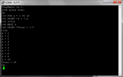
If you put all these together, you can write simple LED blinking programs entirely in BASIC. Check it out:

I might see how far I can take this idea during my vacation.

Addendum: Why does YouTube always choose a frame where my eyes are closed as the default marquee image?

Tiny Basic running on Nanode – Christmas Challenge

As a followup to my post yesterday regarding Arduino BASIC, here’s a contest challenge to extend the Arduino basic to drive the Nanode, an Arduino compatible microcontroller board that extends the conventional Arduino with Ethernet and other cool features. The challenge is to make a good hack using Tiny BASIC: perhaps by extending the BASIC interpreter to include commands for accessing all the additional peripheral devices that the Nanode has. Neat!

Sustainable Suburbia: Tiny Basic running on Nanode – Christmas Challenge

Addendum: It only took me a few minutes of staring at the code to figure out how to add a “DELAY” command that can pause execution. It wouldn’t be hard to add equivalents to the digitalRead, digitalWrite, analogRead and analogWrite. Maybe I’ll give this a try myself over the next few days.

Arduino Basic

Edsger Dijkstra, Dutch computer scientist and winner of the 1972 Turing Award wrote:

It is practically impossible to teach good programming to students that have had a prior exposure to BASIC: as potential programmers they are mentally mutilated beyond hope of regeneration.

While I have respect for his great contributions to the field, in my opinion, this claim falls a bit far afield. In particular, nearly everyone who learned about computers in my generation seemed to through the path of BASIC. BASIC was the lingua franca of the microcomputer revolution, and while I now see it as rather quaint and ridiculous, it provided a step into computing for many people who found that they could indeed regenerate their brain cells in spite of their early exposure.

But does BASIC have any place in the modern world? Well, I must admit, the answer might be “maybe”. Little microcontrollers like the BASIC Stamp have been overshadowed a bit by the Arduino, but I still think that having an interactive interpreter that you can use to access a small computer makes some sense. Having a small language like Tiny BASIC, augmented by a few small additions to (say) allow you to generate sounds or control I/O pins makes a great deal of sense. Thus, without further justification, take a look at this project:

Arduino Basic – User's Wiki!

The code looks pretty nice and tidy, and should be easy to extend. It allows programs of up to 1.4K to be loaded into RAM, which sounds like a trivial amount, but it’s certainly enough to blink some leds, read and write some serial data, and generally exercise some of the capabilities of the chip. Neat project!

Nice article on making an Arduino DDS…

My experiments with generating RTTY signals yesterday made me begin to think about generating RTTY signals with an Atmel/Arduino setup. The obvious way is to use PWM and a low pass filter to approximate a sine wave. While doing a bit of research, I found the following link which seemed to be nearly ideal: it even included an amateur radio application that uses an Arduino to generate the tones necessary to transmit WSPR. It also has a very nice lowpass filter design that can be pressed into service to smooth the PWM output. Stashed for future reference:

Arduino DDS, with WSPR applications

More on the crazy ITA2 encoding…

So, this morning, I was trying to test my understanding of the ITA2 code used in amateur radio teletype communications. I wrote up an encoder, generated some test audio files, and tried decoding them with fldigi. It mostly worked, but I had some difficulty with certain punctuation marks. I was curious what the problem should be, so I dug into the code in fldigi that does this stuff. I found this interesting chunk of code:

[sourcecode lang=”cpp”]

#if 0
/*
* ITA-2 version of the figures case.
*/
static unsigned char figures[32] = {
‘\0’, ‘3’, ‘\n’, ‘-‘, ‘ ‘, ‘\”, ‘8’, ‘7’,
‘\r’, ‘\xb7’, ‘4’, ‘\a’, ‘,’, ‘\xb7’, ‘:’, ‘(‘,
‘5’, ‘+’, ‘)’, ‘2’, ‘\xb7’, ‘6’, ‘0’, ‘1’,
‘9’, ‘?’, ‘\xb7’, ‘\xb7’, ‘.’, ‘/’, ‘=’, ‘\xb7’
};
#endif
#if 1
/*
* U.S. version of the figures case.
*/
static unsigned char figures[32] = {
‘\0’, ‘3’, ‘\n’, ‘-‘, ‘ ‘, ‘\a’, ‘8’, ‘7’,
‘\r’, ‘$’, ‘4’, ‘\”, ‘,’, ‘!’, ‘:’, ‘(‘,
‘5’, ‘"’, ‘)’, ‘2’, ‘#’, ‘6’, ‘0’, ‘1’,
‘9’, ‘?’, ‘&’, ‘\xb7’, ‘.’, ‘/’, ‘;’, ‘\xb7’
};
#endif
#if 0
/*
* A mix of the two. This is what seems to be what people actually use.
*/
static unsigned char figures[32] = {
‘\0’, ‘3’, ‘\n’, ‘-‘, ‘ ‘, ‘\”, ‘8’, ‘7’,
‘\r’, ‘$’, ‘4’, ‘\a’, ‘,’, ‘!’, ‘:’, ‘(‘,
‘5’, ‘+’, ‘)’, ‘2’, ‘#’, ‘6’, ‘0’, ‘1’,
‘9’, ‘?’, ‘&’, ‘\xb7’, ‘.’, ‘/’, ‘=’, ‘\xb7’
};
#endif
[/sourcecode]

Odd. It seems to differ significantly from the “official” ITA2 code. So, I modified my RTTY encoder to use the same encoding. I also discovered that fldigi implements “unshift-on-space”, regardless of what mode you are in, sending a space drops you back into the letter mode. This caused some things to decode improperly until I fixed it.

Now, it seems to work. If you are bored, you could download this overly long and verbose RTTY message (note, you may have to reverse mark and space frequencies, I’m not sure I got that right yet).

An RTTY message, encoded by my RTTY encoder (2.2M WAV file)

Question regarding the ITA2 “Baudot” code…

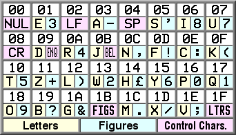
While looking at the hadie high altitude balloon project, I got to thinking about making a microcontroller that could send RTTY. I knew that traditional Baudot (more properly the ITA2 code) was a five bit code with codes designed to switch back and forth between “letters” and “figures”, but I had never looked at the actual matrix. Here is the diagram from Wikipedia:

Tell me, is there ANY rhyme or reason to this layout? It literally looks like they just scattered the letters and numbers onto the codes more or less completely at random.

I was just curious: can anyone tell me what I am missing?

Hadie High Altitude Balloon Project

While listening to the Amateur Radio Newsline podcast this week, I was interested to hear that a group of hams from Ireland had launched a balloon which transmitted digital pictures back from the balloon while it was at altitude, using a version of dl-fldigi. While I was familiar with fldigi, I hadn’t heard of this version, so I did a bit of searching on the web.

First of all, you can find details about the hadie high altitude balloon project here:

Hadie High Altitude Balloon Project

The flickr photostream from the most recent flight of hadie:4 can be found here:

Slideshow of hadie:4 images

Sadly, the balloon had a slower than predicted rise rate (2m/s instead of 3.5) and so overshot England after floating across the Irish Sea and landed in the North Sea. But it’s very cool that we got these live photos back.

Digging a bit more revealed this nice project web page which had many details about the hardware and software they used. They used a serial based camera module previously sold by Sparkfun (now apparently retired), an NTX2 module from Radiometrix which broadcasts on 434.075Mhz, and a cpu based upon the ATmega644P chip. The flight software appears to be written in C, and reads the data from a GPS and the camera module, and repackages it in a custom format called ssdv for transmission over 300/600/1200 baud 8 bit RTTY which can then be decoded by a custom version of fldigi known as dl-digi. Very neat. The radio module that they use has an output power of just 10mw, and yet was successfully decoded over distances greater than 500km. What’s kind of cool about this technique as opposed to (say) the analog Robot32 mode that ARISSAT-1 uses is that the image is broken up into packets, which are transmitted and received independently. The dl-fldigi can send any received packets to a central repository, and thus if any station successfully decodes a packet, then the image can be reconstructed (something that is difficult with analog SSTV).

I didn’t have much to add to this, I just wanted to stash this for later. While the images they got don’t really compare to some of the awesome HD footage that we are seeing shot with GoPro cameras, the immediacy of this seems very appealing, and it’s a good technical challenge.

Cook’s Illustrated Almost No Knead Bread

My early success with making tasty no knead bread has sent me off on the Internet looking for additional recipes. As a complete breadmaking newbie, I have a lot to learn, but luckily, there is lots of good websites to help me understand and extend my tiny skills in this vast topic. The best of these that I have found so far is Breadtopia, which has all sorts of great recipes and many cool videos that will take the mystery out of breadmaking. I of course focused on the no knead recipes, which seem the most accessible to me, but apparently Cooks Illustrated extended this recipe in a couple if interesting ways, notably by adding a small amount of vinegar and beer to the dough. They also have an interesting recipe for a sandwich loaf, which has a tighter crumb and thinner crust. I’ll be trying some of this out over the holiday weekend. If you’ve never made bread before (or even if you have), consider trying this stuff!

Cook’s Illustrated Almost No Knead.

Back to QRSS…

For some reason, I’m getting back into the universe of QRSS, or very slow Morse code. I goofed around with this for a while, writing some software to record audio and produce the necessary FFTs so that you can read Morse from these incredibly long Morse messages, but lately haven’t done much lately.

Hopefully, that will change during my time off for the holidays.

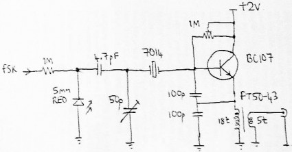
Somewhere in a junkbox, I built this circuit (from Hans Summers, G0UPL):

It’s really just a Colpitt’s oscillator, with a reverse biased LED acting as additional capacitance to “tune” the frequency around the nominal crystal frequency. When I built this circuit, I played around a bit with using an Arduino with an digital to analog converter to drive the LED back capacitance, and that worked fairly well. Here’s a timewarp back to that project, in the form of two of my earlier YouTube vids:


It worked, but I never put it on the air. But I got to rethinking it a bit more, and thought that maybe I’d assemble a new version and see how much I learned. I’ve got some ideas for improvements:

  • Make it “real”. Think about the layout a bit, and built it to be completed inside an (Altoids?) case.
  • The 4.7pf cap is too much to be driven by 0-5v (it induces too much frequency swing). Use a “gimmick” cap in its place.
  • Build in a small “dummy load” (just a 50ohm resistor), and add some test points so you can monitor the supply voltage and current from (say) an Arduino. It would be interesting to monitor temperature as well.
  • Oh, and use an Arduino to key it. Or maybe just an ATtiny.
  • Spend some time thinking about solar powering it.

I also was considering making a better dedicated antenna for it. I suppose I could just use a 30m dipole, but I think it might be fun to try something a bit smaller. Alan did some experimentation with a center loaded short dipole which might be fun, but I’m still pondering that.

The micro-power transmitter is fun, and unlikely to cause anybody any anguish, but might also be a bit hard to get any real DX with. So, I started thinking about what I needed to change. Higher voltage, to generate more power. A buffer and power amplifier to generate maybe 100-200mw. And a harmonic filter, so I could be a good citizen. But then I realized something: Hans was offering a kit that had all of those features already, and for about $15 US. So, I’ve got one of those on order too.

I hope to be on the air come the New Year. Stay tuned.