I was over at the CVS repository today, and saw that they had some small strings of fifteen LED Christmas lights on sale for a paltry $.99 (if you used your CVS discount card). That was simply too much to resist, so I got a couple of strings, and thought that I would use them for a Christmas related electronics project of some sort.
And, of course, it provides a reason to test your basic electronics knowledge as well. (Forgive my more technologically saavy readers, this is gonna be pretty basic, but I found it fun to go through the mental exercise).
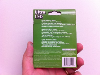
First of all, here are photos of the box they came in, just so we are all on the same page:
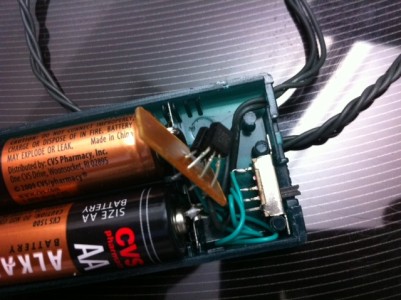
When you pop them open, you’ll find a small greenish plastic box that holds the batteries, and a string of fifteen LEDs wired into it with green wire. The box has a small switch on it, which if you stare at you’ll see has both an OFF and an ON position, but it can also be set half way to enable a blinking function. Popping two batteries into the case and flipping the switch had the desired effect: Christmas lights!
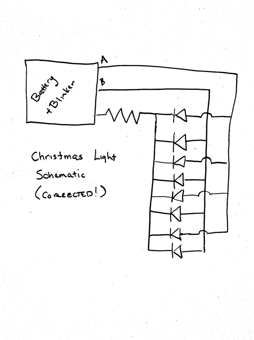
So, I started staring at them. There are three wires coming out of the battery box. Each LED appears to have five wires operating in its vicinity. One bypasses the LED, and four other wires sprout from each LED (except for the very last one on the string, which just has two connections. A few minutes of thinking reveals that the LEDS must be wired in parallel, with a circuit that looks very much like this:
Ed. note: Mike pointed out that the original schematic was in error. This has been updated.
The lines labelled A and B are just two power lines: each carries power to half of the LEDs. In the “blink” mode, power is applied to only half of the LEDs at a time. Staring inside the box, it appears that there are two discrete plastic cased transistors wired together: my guess is that they are a classic multivibrator circuit. I’ll verify that later.
Okay, enough of boring reality, let’s try to get to the exciting math.
First of all, the package says that we can get “120 hours or more” from one (presumably) set of alkaline batteries. That seems like excellent battery life, but how realistic is it?
First of all, how much power is in a pair of AA alkalines? Wikipedia says we have about 1800-2600 mAh. I bought some cheap AAs from CVS, so let’s say we are in the middle of the range, about 2200 mAh. Naively, to last 120 hours, the current draw can only be 2200 / 120 or about 18ma (this isn’t quite right, but it’s close) which works out to about 1.2 ma of current per LED (did I mention that the LEDs are wired in parallel?). The total power consumed is about 50mw. If we assume the voltage drop from the LEDs is around 2 volts, we need we need to have a series resistance of about 1 v / 18ma or about 55 ohms. It can be a tiny one, since the power consumed is very small.
All this presumes that they were all in parallel. In reality only half the current flows in each of the A and B circuits, so in blink mode, I suspect the power consumed will be cut by one half (ignoring the power consumed by the multivibrator, which should be very low).
But here’s the good thing! The current draw is low enough that it should be possible to power these lights directly from an Arduino, without any additional switching transistors or the like. My intention is to power each of the two strands with a PWM signal, to allow independent fading and glowing.
But I don’t trust my math enough (nor the specified 120 hour life) to just hook this up randomly, so I’ll be doing a little dissection when I get home tonight, to verify that my calculations are roughly correct. Stay tuned!
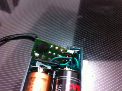
Addendum: I took a closer look at the tiny circuit board inside the battery case, and was somewhat surprised to see its inner workings hidden under a blob of epoxy. Two driver transistors do appear on the top side. As far as I can tell, no caps or inductors are visible anywhere:
Addendum2: Last night I put my multimeter in series with the batteries in this circuit, and measured a current draw of 40 milliamps in its “steady”, non-blinking mode. That means that the 120 hours on two AAs quoted on the box is likely a fiction, a life of more like 55 hours would seem to be more likely. In blinking mode, the current draw seemed to vary between 20ma and 30ma, but my meter wasn’t able to integrate the current to a stable value.
I’m thinking that I’ll resurrect the circuit that I used for my ATtiny13 powered pumpkin to drive these LEDs. The ATtiny13 has two PWM channels, which could be used to drive the two LED channels separately, allowing some cool color fading effects. I could probably even salvage the case to hold the batteries. Stay tuned.


