A couple of my projects have used the tiniest of the Atmel ATtiny chips: the ATtiny13. I have written one or two programs in assembler for these chips, but I prefer to work with avr-gcc whenever possible. What’s amazing is that you actually can use a sophisticated C compiler to generate code for such a tiny chip (only room for 512 instructions).
Yesterday’s project was to implement a small QRSS beacon controller, similar to one’s sold by Hans Summer as part of his QRSS kits. He actually published his code, so I could just use that, but I found it a little bit obscure, and thought I could do something, well, if not better, at least less obscure to me. I wanted to retain the basic interface (Hans’ chip provides a sidetone on one pin, a key on another, and uses three pins as an input to select one of eight speeds). The basic loop fetches a pattern of dots and dashes, looks up the speed from the input switches, and then sends the pattern of dots and dashes. Easy peasy. I’ve written similar Arduino code before. Toggle pin high, delay, toggle pin low, delay, out goes a dot or dash.
But when I tried to use the _delay_ms() macro, I found that the codesize I had used grew enormously. It appeared to be dragging in a bunch of floating point arithmetic routines. I had used this function on my Christmas tree hat project without incident: what was going on?
Well, first of all, it appears that _delay_ms takes a floating point value as an argument. The compiler is smart enough that if the value passed to the function is a constant, it unfolds the code into a simple integer only loop. But if you use a variable as the argument (as I do, since the dit times are varying in length) you end up dragging all the floating point baggage into your code. It seems ridiculous to use floating point in this situation.
I got around this by noting that in my case, all my delays were multiples of 100ms. So, instead of just calling _delay_ms(n*100), I implemented the delays as a simple loop which executes _delay_ms(100) multiple times. Code is small, all is well.
You would think that a small, integer only delay would be possible. Oh well.
Fellow hacker Eric Smith has released the code for an 8080 simulator. I spent a few hours hacking my own 8080 emulator a few months ago, and at least got it to run Tiny BASIC, but I was never quite successful in getting it to boot CP/M. Among some of the problems were that I wasn’t quite assured that I implemented all the opcodes properly. There are some programs which act as an “opcode exerciser”, and produce a series of checksums that you can use to detect bugs, but I found that even well known simulators like simh didn’t match the output from real 8080s. It appears that Eric has done the heavy lifting and figured this stuff out, and released the fruits of his labor as a GPL’ed reference implementation, checked against the actual running against an original Sol20. I’ll have to go back sometime and see where my own simulator has gone awry, but until then, thanks Eric!
Well, the fact is I had heard of doing that. It’s not really hard to rig something that will convert the RS232 level from the GPS into TTL levels for the Arduino. It just takes a single transistor inverter: you rig an 10K resistor from the RS232 signal to the base, a 1K resistor from 5v to the collector, and then ground the emitter. Tap the transistor on the emitter side, and voila! It works. I rigged this up on the breadboard and checked it on the scope, and sure enough: 5v and 0v. I then coded up a simple sketch which used the SoftwareSerial library: it instantiates a serial port, then copies bytes when available to the normal Serial output device. Once I remembered that my GPS output at 4800 baud, the program worked flawlessly.
After I got this working, I gave the other direction a tiny amount of thought. I couldn’t think of a good, simple way to convert the TTL level to the negative levels without using some kind of charge pump, or a negative supply. But there is a cute trick you can use, that I discovered while surfing for alternative circuits: check it out. The trick is that if you are operating half duplex (only one side of the transmission transmits at the same time), the transmit line will go to the negative state. So, if you need to output a negative value, you simply swipe the voltage from Tx side of the RS232 line. That just takes a PNP transistor. Very cute.
Addendum: the receive circuit looks the same as mine, except they add a diode. Novice that I am, I don’t get why it is necessary or desirable. My circuit seems to work fine without it: can someone with experience tell me why it’s a good idea?
Addendum2: The MAX232s aren’t wasted: I am using it as an opportunity to learn Eagle and design a simple but still useful PCB. I’ll still be working on that.
I used to be an electrical engineer like you, then I took an arrow in the knee.
(If you don’t get this, google for “arrow in the knee”, and guess what Xbox game I spent the morning and afternoon playing instead of working on something cool.)
I’ve had a number of projects that could benefit from adding a GPS to an Arduino. I’ve got a few old GPSes lying around: in addition to the normal handheld and car windshield Garmin models, I have an old Garmin 18 and an ADS-GM1 from Argent Data Systems. They are the guys that make the Open Tracker (have one of those kicking around somewhere too). It’s a pretty respectable little GPS, and since I wasn’t using it for anything else, I thought it would be great to hook one up.
Except, well, it doesn’t use TTL signal levels for it’s serial connection. I double checked it by hooking it up to my scope, and have a peek:
Yep, -6v to 6v will not do. So, a few days ago, I ordered some Maxim MAX232CPE drivers from Tayda Electronics (great price, only $.33 each). I also intended to order some PCB mount DB-9 connectors that would mate with these, and do a small PCB that could be plugged into a breadboard, and then the DB-9 on the ADS-GM1 wouldn’t need to be modified. But sadly, I ordered the wrong part, and so that project is a teensy bit on the back burner. But pretty soon, I’ll get that all sorted out and a number of my Arduino projects will be able to benefit from accurate position and time.
This is a very cute hack that does something which I thought was impossible: an implementation of an FM transmitter that has exactly two components: a battery and an ATtiny45 microcontroller. It’s brilliantly obtuse and cool:
The basic idea is to trick the internal oscillator of the Atmel to run at 24Mhz. An internal PLL will run at 4x that frequency, which is a 96 Mhz signal (right in the middle of the FM broadcast band). By varying the frequency up and down, you can generate an FM modulated signal. Beyond clever. Very cool.
I was reading up on resistor ladder DAC circuits on Wikipedia, and came across the Unequal Resistor R-2R Ladder Optimizer. It’s very neat! You can enter the number of bits you need, and the values of the pile of resistors that you have measured from your bench, and it will produce an optimized design using those values. When you are making an 8 bit DAC, the normal variation in a 5% tolerance (or even a 1% tolerance) can cascade to keep you from being entirely linear, or even monotonic, so doing this optimization seems enormously practical. As a bonus, once you have your DAC simulated using the Falstad Circuit Simulator, which is itself an enormously cool thing: a Java based circuit simulator that can accept new models encoded on the URL! Paul Falstad has a huge number of other cool educational Java applets, check it out!
Dave Jones (@eevblog) tweeted:
https://twitter.com/#!/eevblog/status/162530266513014784
And indeed, he’s right! WDC (the Western Design Center) has made a new version of the 6502 available at mouser.com. It’s a 40 pin DIP package, listed at $6.95 in quantity one, and can be clocked up to 14Mhz. It sends my mind racing back to the days of Star Raiders on my Atari 400. Not sure why it would be a good part to use other than nostalgia, but I’m bookmarking for future consideration.
I’ve often thought that creating a replica of an early Baird mechanical television, or televisor would be a fun project. But when starting, you immediately run into the problem of how to generate material for them. The Narrow Band Television Association standard format specifies 32 line format at 12.5 frames per second (400 lines per second). It also specifies an aspect ratio of 2/3, which means that if we are using square pixels, we want to resize to an output resolution of just 32×48 (yes, images are taller than they are wide). I thought about using some old Coronet films like Are You Popular as appropriate source material, and worked to create an ffmpeg command (my goto Swiss Army knife of video conversion) and came up with the following command line to crop the existing video into the 4:3 video into a 2:3 video and resize it to 48×32:
You can then play televisor.mp4 and see (in a very small window) what televisor video might look like. But how can we turn this into a sound file like we need to drive a televisor? Well, we need 400 lines per second. A CD’s natural format is 44100 Hz. That’s 110.25 samples per line (bummer, it doesn’t divide evenly). We could round it down to 110 or so (not bad) or we could generate our samples at 48000 hz instead of 44100 and use a high quality downsampler to generate the final audio. Either is acceptable. We can make life easy on ourselves by using ffmpeg to generate individual video frames with the the right number of vertical samples (either 110 for 44100 or 120 for 48000) and generate .pgm files (which are very nearly the raw 8 bit sample values we need):
With a little more work, I can transpose the files (so they are in column order as expected by the televisor) and then add the sync pulses we need. I’ll play around some more with this tonight, and then try it and verify my understanding using the NBTV viewer. Then, perhaps on to building a televisor.
While researching something completely different, I found Adrian Freed’s very cool page with code to generate high quality sine waves using PWM on the Arduino. This code could serve as an audio frequency signal generator, or as the basis of a computer music project. It also demonstrates some non-trivial Arduino wizardry in dealing with PWM interrupts and the like. Bookmarked for future reference!
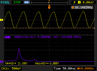
This week, I splurged and bought myself a new piece of test equipment: a Rigol DS1102E 100Mhz oscilloscope, and compared to my old 25Mhz Philips (which was indeed a great buy at only $20) it’s very, very cool. Among the most neat features that I’ve started to use is the ability to do screen and waveform grabs, and save them to a little USB flash drive. To gain some experience with the new gadget, I dusted off a version of Hans Summers’ low power QRSS beacon that I had breadboarded up a chunk of copper clad. Here’s the video I did about it (and a glimpse of my old scope too!):
The oscillator operates around 10.14 Mhz, and I couldn’t really see any detail of the waveform with my old scope: it just didn’t have the necessary bandwidth. But with the new scope, the situation is quite a bit different. I powered the oscillator up with a pair of D cell alkalines. I adjusted the bias potentiometer for the best looking sine wave, and it’s not too bad. Here’s a screendump of its best looking sine wave, and the FFT of that signal below. You can see that there is a bit of a second harmonic (due mostly to the asymmetrical waveform) but that it’s overall pretty good. The peak to peak voltage is around 2.18 volts, which is about a 12 mw.
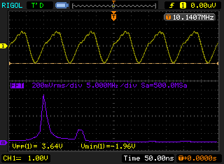
By adjusting the bias potentiometer, you can get more power out: the peak to peak voltage rises to around 3.64V, for an output of around 33mw. But the waveform looks much less uniform, more energy scattered into the second harmonic.
I’m really liking this. I will probably make some additional changes to this circuit tomorrow, but having a good scope to examine how the changes affect the performance is really awesome. A great investment in my electronic education.
I’ve been trying to do a bit more Arduino programming and interfacing lately. Nothing too difficult, but just trying to expand my junkbox and my skills so that I can quickly prototype new ideas and expand the kind of projects that I can tackle in the limited time that I seem to have for playing around.
I have written programs to use an Arduino to blink or beep Morse code before, but the programs were meant to control beacons, where they might just send the same message over and over, which I just compiled into the program. Today’s experiment did two things: it reads and buffers keystrokes from an old IBM PS/2 keyboard which I rescued from exile in my garage, and it actually keys my ham radio transmitter (a Yaesu FT-817ND) using a 4N31 optoisolator.
Most keyboards that you get today are interfaced via the Universal Serial Bus (USB). That’s kind of cool, but it’s also a bit of a travesty, since they require a lot more code (and a lot more knowledge) to interface what is ultimately a pretty simple device. Back in the old IBM AT days, keyboards were equipped with a large 5 pin DIN connector, and would transmit “scan codes” represent each character along a simple serial bus. The IBM PS/2 shrunk the connector to a six pin mini-DIN connector, but retained almost all the other features.
But if you want to do a tidy job, you’ll need some extra bits and pieces to hook them to your Arduino. Luckily, Sparkfun has a couple of cheap bits that will make it easy. I ordered some 6 pin MiniDIN connectors from them, along with a tiny $0.95 breakout board which you can tack together along with some header pins to make a little breadboard friendly connector. You need four connections: 5V, ground, and a clock and data line, which I connected to pins 3 and 4 on my Arduino.
You’ll also need a library. Yes, you could roll your own, but that would have added hours to this simple project. Instead, I chose this one, more or less at random from a number of possibilities. It seemed to work fine, and compiled properly even with my Arduino 1.0 setup. The code actually comes from the guys who make the Teensy, but the code works fine on regular Arduinos.
Then, I wrote the code. I wanted the user to be able to type ahead of the sending, so I needed to implement a ring buffer to store chars (currently up to 128) which I coded up from scratch in the simplest way possible. The way I used to do Morse sending was to set the output pin to be HIGH, then delay(), then set it to LOW. But we want to process new keystrokes and add them to the buffer as soon as you can. So, I implemented my own “delay” function, which loops to find new characters and inserts them in the buffer while waiting for the timeout. This seems to work pretty well.
Without further explanation, here’s the code:
[sourcecode lang=”cpp”]
#include <PS2Keyboard.h>
// _____ _ _ _ _ __ __
// |_ _| |_ ___ /_\ _ _ __| |_ _(_)_ _ ___ | \/ |___ _ _ ___ ___
// | | | ‘ \/ -_) / _ \| ‘_/ _` | || | | ‘ \/ _ \ | |\/| / _ \ ‘_(_-</ -_)
// |_| |_||_\___| /_/ \_\_| \__,_|\_,_|_|_||_\___/ |_| |_\___/_| /__/\___|
//
// _ __
// | |/ /___ _ _ ___ _ _
// | ‘ </ -_) || / -_) ‘_|
// |_|\_\___|\_, \___|_|
// |__/
//
// Version for the PS2 Keyboard
// using the library from http://www.pjrc.com/teensy/td_libs_PS2Keyboard.html
//
// Written by Mark VandeWettering K6HX
//
// This is just a quick Morse keyer program.
//
////////////////////////////////////////////////////////////////////////
//
// Here is a queue to store the characters that I’ve typed.
// To simplify the code, it can store a maximum of QUEUESIZE-1 characters
// before it fills up. What is a byte wasted between friends?
//
////////////////////////////////////////////////////////////////////////
char ltab[] = {
0b101, // A
0b11000, // B
0b11010, // C
0b1100, // D
0b10, // E
0b10010, // F
0b1110, // G
0b10000, // H
0b100, // I
0b10111, // J
0b1101, // K
0b10100, // L
0b111, // M
0b110, // N
0b1111, // O
0b10110, // P
0b11101, // Q
0b1010, // R
0b1000, // S
0b11, // T
0b1001, // U
0b10001, // V
0b1011, // W
0b11001, // X
0b11011, // Y
0b11100 // Z
} ;
if (!queueempty())
send(queuepop()) ;
}
[/sourcecode]
To key the transmitter, I used a 4N31 optoisolator. This code uses pin 13 to key the transmitter, so I wired it to pin 1 on the optoisolator, passing through a 1K current limiting resistor, and pin 2 ground. Pins 4 and 5 are wired to the tip and shield of a 3.5mm socket, which I then connected to the FT-817 key input using a 3.5mm stereo cable I had lying around. I could have used a little NPN transistor to do the keying, but the optoisolator keeps any current from the radio from circulating in the Arduino (and vice versa) which is a nice little insurance that nothing will zap either my radio or my microcontroller.
Here’s the resulting project:
Feel free to drop me a line if you find this code to be useful. Let me know how you adapted it to do something cool in your shack or lab.
Addendum: Friends Atdiy and Whisker of the tymkrs empire made a similar project a while ago, except that they used a board based upon a Propeller board, which does a lot of what my project does as well. If you like the Propeller instead (and if you’ve been following my blog and reading about WA0UWH’s beacon, why wouldn’t you?) you might check out their video:
I was tinkering with a small electronics project (article and video to come) and needed a sound output. Digging around in my junkbox, I found one of these piezo speakers, and decided to use it, driving it with a square wave from my Arduino:
My initial test was supposed to be 700 Hz, but it sounded very high. I recorded a sample with Audacity and looked at the spectrum, and sure enough, it’s principle frequency was at 2100Hz. I then looked at the driving signal using my Rigol DS1102E (did I mention I got a new scope this week?) and sure enough, it was a nice 700 Hz square wave. Apparently the specifications on this little piezo element weren’t kidding: it has almost no frequency response below 1500Hz, so all you end up hearing are the third harmonic. The fifth harmonic is actually pretty weak too, so you end up with a pretty even sine wave, just at the wrong frequency.
I guess if I want higher quality sound out of this thing, I’ll need to rig a real speaker.
I share an interest in old computing technology with several of my friends and readers. An interesting sub-topic within this vast area is the world of computers based upon relays. In the last couple of days, I found cool links to two different relay based computing projects, so I thought I’d pass them along.
First is Jon Stanley’s Relay Computer Two. Consisting of 281 relays, it boasts an 8 bit data bus and a 16 bit address bus. His website gives the kind of dense, technical information that I like to see from a project like this. You’ll see how he implements adders (using Konrad Zuse’s design which constructs a one bit full adder out of two 4PDT relays). Very neat. Lots of cool details. It clanks along at less than 30 cycles per second. Yes, it uses solid state memory (as almost all amateur reconstructions do, it’s simply to expensive to do otherwise) but the result in a clicky, clanky marvel. Check it out (and make special note of the enormous capacitor in the power supply):
Then there is Rory’s awesome series of relay based computers, culminating in the TIM-8. There are all sorts of awesome laudable features in this build. He didn’t want to “cheat” and use solid state memory, so he struggled to find solutions. He ends up storing programs on paper receipt tape as a series of black and white lines which provide control signals to the rest of the computer. These are then loaded onto a motor driven spindle and read by a series of phototransistors (I think, not clear). The tape is rewound and replayed during program execution. Very cool. He also constructed his own solid state memory out of capacitors, with a density of about 9 bits per cubic inch. Very, very cool. Here’s one of his videos, but search around on his site, he has more:
This is just a plug for a cute little pair of gadgets that I got the other day.. If you are like me and use solderless breadboards to experiment with stuff on the Arduino, you end up with the Arduino and the breadboard connected by a hodge podge of wires, and if you accidently tug on a power supply cord or the USB cord, half connections come undone. Or, you do all this experimenting on the dining room table, and when you have to clear it away for dinner, all sorts of wires become undone. Frustrating. Even annoying.
So, I took out an insurance policy against annoyance and frustration and ordered a protyping board for the Arduino Uno from TAUTIC.com. TAUTIC Electronics LLC is one of those cool little bootstrapped companies that have chosen to embrace the Open Source Hardware ideas and offer products of interest to tinkerers like myself. This prototype board is basically just a solderless breadboard bonded to a blue plastic backer, with the holes properly drilled to attach an Arduino Uno and the necessary hardware. He also makes version for the chipKit microcontrollers manufactured by Diligent.
While I placed that order, I decided to also give one of his dual output breadboard power supplies a try. For $9, you get a nice little board that plugs into a prototype board and provides 5V on the top rail, and 3.3V on the bottom rail. Very spiffy. The boards were shipped to me literally on the day I ordered them, great customer service. Jayson has a number of other cool boards, including some thermocouple boards and a PIC based development board. Check his store out and see if there is something that catches your eye.
We’ve all heard it (and most of us have said it): “X is just a dumbed down for the masses.” Heck, I came dangerously close to saying it myself in today’s earlier rant. But I didn’t say it, and I try not to, because I think it’s not really very useful.
First of all, if you really are a beginner, you probably need things to be dumbed down, at least a little. For instance, as a relative beginner working to self-educate himself in the field of electronics and RF design, I learned that diodes pass current in one direction, but not the other. This is a “dumbed down” version of diodes: they actually have a forward voltage drop, and it’s only when that forward voltage drop is exceeded that current passes. But that too is a dumbed down version of what diodes do. The forward drop isn’t constant, it depends on things like temperature. Also, there is actually a curve that relates voltage and current, they don’t just snap on. But that too is just a “dumbed down” version of what a diode is. And so on, and so on.
The fact is, these “dumbed down” versions of the diode are very useful: they do convey some bit of useful information and begin to give us some experience and intuition about reasoning about circuits that contain diodes. The only thing that is bad is if we envision that our “dumb” understanding of diodes was a complete understanding of diodes. Then, there would be circuits and behaviors that we simply couldn’t understand, because the real diodes are a bit more subtle than our dumb version, whatever level of understanding that might actually be.
But more than that, when we say something is dumbed down, we stray dangerously close (and often well beyond) calling the people who may use these simplified models as “dumb”. That simply isn’t productive, and runs counter to what I view as the purpose (and mostly successful achievement) of getting people interested in computing and electronics. The Arduino is successful because it does “dumb down” things enough for the people to experience success, who might otherwise have been frustrated and annoyed. When I hear people say that the Arduino is “dumbed down”, I really hear them telling people who use them (or even more tragically, might have used them) that they are stupid. I don’t want to call people stupid, especially those who might actually try something that I enjoy, and inspire me to do better work.
The problem I was trying to make clear was not that the Arduino was “dumbed down”, but that the default development environment was a path that eventually kind of dead ends: to gain any real expertise and fully use the power underlying the $2.50 piece of silicon at it’s heart, you almost need to start over: perhaps by using assembler as some has suggested, or perhaps just by using avr-gcc with avr-libc. You have to learn about interrupt vectors, and the hardware resources, because the particular abstractions that the default development enviroment present rob the underyling hardware of its power. To give another example, no less a luminary than Edsger Dykstra scolded a generation of computer science instructors and students that the BASIC programming language was a fatal disease from which they would never recover. It wasn’t true. For many, it was the only programming that they ever learned, but that wasn’t a bad thing. For many in my generation though, it was a stepping stone to an exciting and profitable career.
Don’t bother saying something is “dumbed down”. It’s pointless. Your understanding of almost anything worth knowing is almost certainly “dumbed down” from its reality. Revel in complexity. Don’t be ashamed that you don’t understand everything today: you won’t understand everything tomorrow either, but with luck, you might understand more than you do today.
Now, if I could develop a slightly less dumbed down idea of how FETs work, I could perhaps understand the behavior of my QRSS beacon a bit better. So that’s what I’ll work on for the rest of the evening…


")