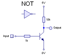
Yesterday, I mentioned Rory’s excellent introduction and exploration into DTL logic. He covers some of the basics here, including circuits for all the basic gates: AND, OR, NOT and NAND. The AND and OR gates are interesting, because they consist entirely of diodes and resistors. They do have the drawback that they are “lossy” (the technical term is non-regenerative). They experience a voltage drop across them, so they can’t be cascaded forever, as the voltage drop continues with each gate, and they ultimately lose the ability to compute effectively. The NOT and NAND gates on the other hand use a typical bipolar NPN transistor, and use the amplifying capability of transistors to regenerate the signal.
I was interested in a couple of things about the circuit though, so I fired up LTSpice for a little computational experiment.
I have played around with simple inverters like this one, which Rory mentioned which I always thought of as an effective inverter. But Rory mentioned that it was unable to run at higher speed (say, around 1Mhz). I was also interested in how the choice of diode affected the circuit.
So, I built it. Rory used BAT42 Schottky diodes, which weren’t in my component catalog, so instead I substituted a 1N5818 diode.
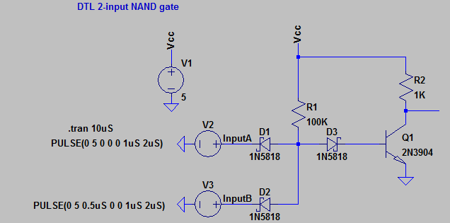
And sure enough, it works pretty darn well. I coded up a 500kHz clock, and the output looks pretty clean. I fed it two pulse trains one delayed with the other, and it looks pretty good.

If you substitute some of the cheap diodes I have on my bench (like a 1N914 or a 1N4148) you can see that it works pretty well at frequencies around 1000Hz, but fails miserably at frequencies of 1Mhz. Ditto for the simplified inverter circuit we looked at above: it simply can’t function at 500khz. Superimposed with the NAND pulse train, here is the output of the simplified inverter wired to InputA. As you can see, the input pulses just turn into a feeble triangle wave.

I suspect that thinking about why this is will lead me to a much more robust understanding of transistors.
Hi, regarding performance of DTL: you might need to implement tricks from this page: http://electronics.stackexchange.com/questions/15056/prevent-high-side-bjt-saturation (namely antisaturation diodes)
Hi Mark,
I’ve tried simulating this on LTSpice but with diode D3 removed.
The reasoning behind this is that the Schottky input diodes won’t allow the voltage on the base to get anywhere near 0.6V. I’m going to make up this configuration for real – and see how it performs. I’ll try using BC846B transistor and BAT54A (double diode with anodes commoned).
BTW – your output traces: I think that for a Nand, it should only go low, when both inputs are high. Have you accidently attached the wrong trace?
Ken
Looking promising.
I only had some 1N5817 schottky diodes and a BC547 available, but on standard breadboard this configuration still performs the nand function at 8MHz.
I lowered R1 to 50K and R2 to 220ohms in order to get a better overall waveshape.
Charge storage in the base region means that these are slow to turn off, and this was noticeable in the rising edges when the output climbs from low to high. Lowering the pull-up resistor to 220R helped speed up this ascent, but at the expense of current consumption. 5V flowing into a grounded 220R resistor is at least 22mA per gate.
I’m going to try this with the surface mount diodes and transistors on a bit of perfboard, without all the stray capacitances of the breadboard. If I can make a flip flop toggle at even 1MHz, using this approach – I’ll be happy.
Ken