I’m having lots of fun with my Raspberry Pi, and I’ve decided to launch one of my crazy spare-time projects: inspired by this article detailing the construction of RUDEBOT, a kind of mobile tablet robot, I decided to build a robot of my own. But, anything worth doing is worth changing and adapting, so I thought I’d put my own spin on it, and use the Raspberry Pi and an Arduino combined to provide the brains of this robot.
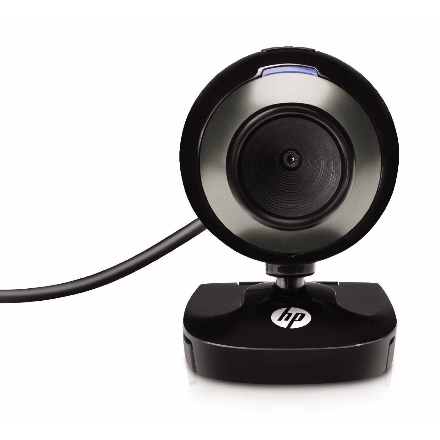
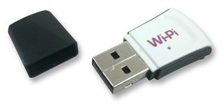 The original incarnation of the RUDEBOT used an Arduino and a WiFi shield. I didn’t like this approach because the WiFi shield is, by all accounts, fairly buggy and limited, and the actual cost of the shield is rather high. It dawned on me that I could buy a Raspberry Pi and a WiPi (the tiny USB 802.11n dongle you see on the right) for less money, and I’d have the advantage of also carrying a full Linux computer on board. I could turn my incarnation into a kind of mobile hotspot, which seemed like it might be a fun thing to try. I would still use the Arduino to handle the basic motor controls with commands sent over a serial port from the Raspberry Pi. Having that much hardware on board makes all sorts of software possible.
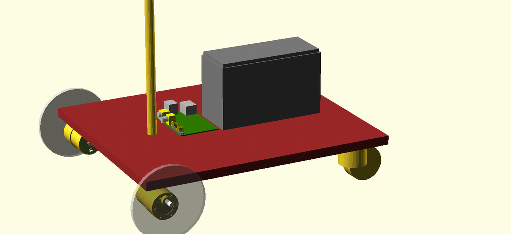
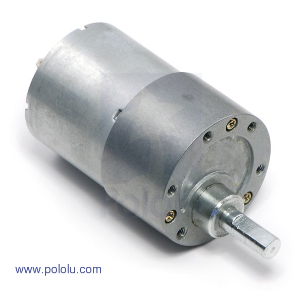
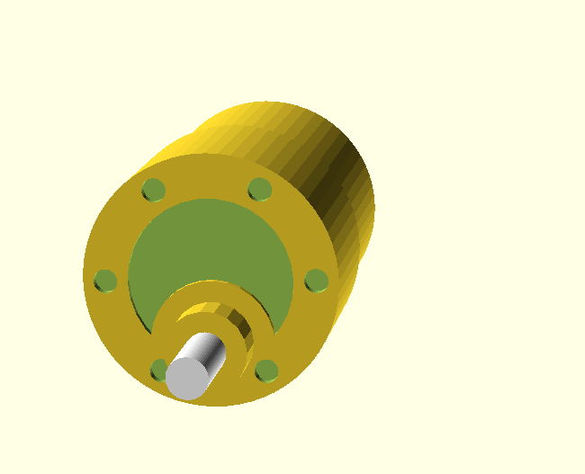
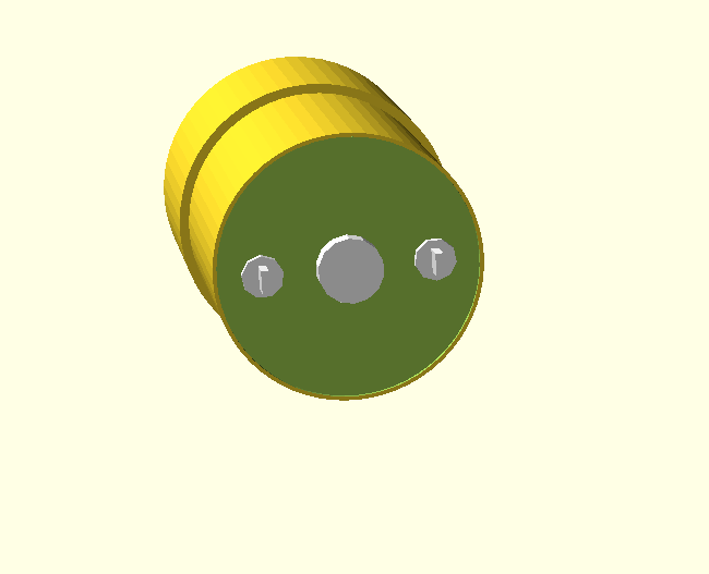
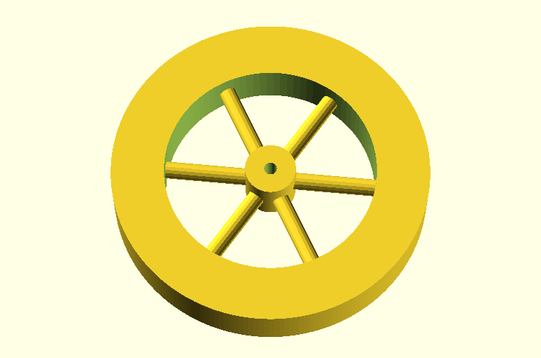
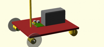 While waiting for parts to arrive, I just sort of began doodling using OpenSCAD to design the basic layout. I built CAD models for the motors and the platform, and selected a 12V 7 amp hour SLA battery. And then… began to think about power.
The documentation says that the Raspberry Pi can consume up to 700ma of current while running. Often, you’ll see that whenever anyone adds any significant USB peripherals to a Pi, they use a powered USB hub. In theory USB devices are supposed to be able to request 500ma of current from the host, but the Raspberry Pi (the second version, the originals ones had even lower power capabilities) has fuses which limit total current at 1A. So clearly, power hungry peripherals can require additional power, and a powered hub is the common solution.
But which peripherals are power hungry? In particular, it would be great if I could hook up the WiPi wireless dongle without having to provide additional power. So, I set out to research whether it was feasible. I saw three ways to proceed:
- Simply try it. If it works, then it works. Hard to argue with that, but it doesn’t tell you a lot about what the limits are. Would adding an additional keyboard/bluetooth/mouse push it over the edge? Undisciplined trial and error doesn’t seem like a good approach.
- Try it, but measure the current required. This seems like a better approach, and gives you hard data. Basically I’d need to tap a microusb cable so that I could put in my trusty multimeter, and I could measure the current directly. I probably will do that soon.
- Try to research how much current these things are spec’ed to use.
The last is easy to do when you have an iPad in front of you during lunch, so that’s of course what I did. But the figure that I’m interested in (power consumption) is not very often listed for USB peripherals. But it turns out that USB peripherals are supposed to give some hints to the host about how much power they require. If you plug in a peripheral to your Linux box (including the pi), you can simply use the command “lsusb -v” to get a dump of all the USB devices, and see what the driver for the hardware thinks it needs.
So, I did just that. I plugged my WiPi into the powered hub, and had a peek. Here’s the dump, most of which is pretty uninteresting, but which contains the Max Power…
Bus 001 Device 008: ID 148f:5370 Ralink Technology, Corp. RT5370 Wireless Adapter
Device Descriptor:
  bLength                18
  bDescriptorType         1
  bcdUSB               2.00
  bDeviceClass            0 (Defined at Interface level)
  bDeviceSubClass         0
  bDeviceProtocol         0
  bMaxPacketSize0        64
  idVendor           0x148f Ralink Technology, Corp.
  idProduct          0x5370 RT5370 Wireless Adapter
  bcdDevice            1.01
  iManufacturer           1 Ralink
  iProduct                2 802.11 n WLAN
  iSerial                 3 1.0
  bNumConfigurations      1
  Configuration Descriptor:
    bLength                 9
    bDescriptorType         2
    wTotalLength           67
    bNumInterfaces          1
    bConfigurationValue     1
    iConfiguration          0
    bmAttributes         0x80
      (Bus Powered)
    MaxPower              450mA
450ma. Ouch. That seems like a lot. I find it kind of hard to believe that such a tiny transmitter can pull that much current without melting itself (it’s tiny). So, I’m left with some questions:
- Can the WiPi really pull that much current?
- Can I use it without plugging it into a powered hub? Some people do seem to be doing that, and have even said that it doesn’t work properly when plugged into some powered hubs.
- I’m also interested in hooking an Arduino to the Pi. How much current can the Arduino pull?
- Ultimately, I probably will want to power all of this equipment with my 12V SLA battery. What’s a reasonable solution to powering the Pi, Arudino and potentially a powered hub? I’m looking for quick and dirty, but also reasonable and reliable.
Any hints from robot/power/Raspberry Pi experts are welcome, here or via twitter @brainwagon.
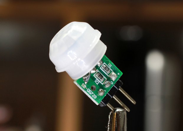 A few days ago, I heard that Jayson Tautic (@tautic), manufacturer and purveyor of a interesting electronic prototyping goodies, had put up an interesting offering: a small PIR (passive infra red) motion detector. I’m always up for a new sensor to play with, so I ordered a pair for fun, and they arrived on Friday.