Monthly Archives: March 2013

My Arduino bumper, with actual prints!

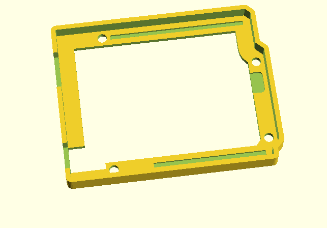
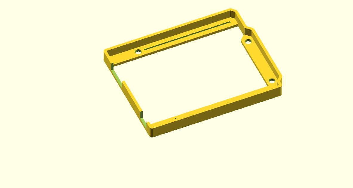
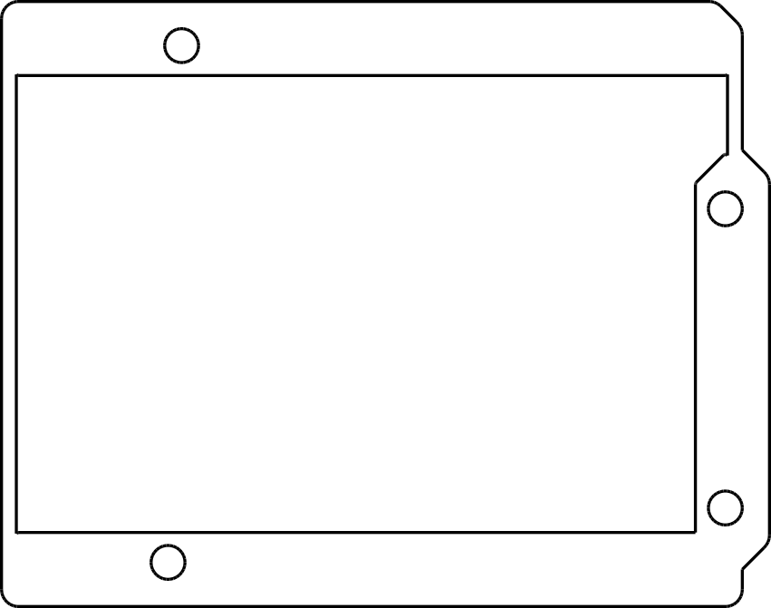
Okay, our Replicator 2 went back online this week, and I decided to give printing my Arduino bumper another try. Since the last time, I have revised the program and code a couple of times. I was concerned that the various bits of solder protruding from the bottom of the board would need extra relief cuts. As I tried to account for more and more of these, I decided I did not like the design especially well, so I took a different tactic: I decided to make the bumper’s walls as thin as possible, and only include an area around each of the Arduino bolt holes. This minimized the amount of material needed, and also means that it could be printed more quickly.

And so, I printed it out. I use the Makerbot software, set for the Replicator 2, once using medium quality (with a print time of about sixteen minutes) and once using the high quality (print time of nearly an hour). I used 25% infill for both, I wanted to make sure the outer and inner shells were sufficiently bonded. I then printed it!


I had a little spare time, so I also decided to print out a simple model I made in OpenSCAD: a cross section of the Clark Y airfoil, with 1/8″ thickness. It turned out rather well, fairly smooth, and with only a minor divot at the trailing edge. It was also reasonably sturdy, I don’t think I could crush it in compression with my hand, although it’s impact resistance is unknown. I also took the time to download a model of the chicken from Minecraft and print that. It comes in four parts, which we could then glue together. I had no real failures:


But there were a few issues.

First of all, my Arduino bumpers were a pretty tight fit.

I coded in a clearance of 0.008″ around the nominal board size, but that was simply not enough. I think I’ll expand that to 0.012″ or even 0.015″ next time around. I was able to press fit one of my OSEPP Arduino boards into it, but just barely, and only by shaving a small amount off one corner of the board with an Exacto knife. I also think I should thicken the bottom slightly: if you used this shield to bolt against a conductive surface, some of the solder joints on the bottom of the board could still short out. I am also thinking of widening the channels cut for the USB and DC jack a small amount, they fit, but just barely. An additional 0.02″ of an inch would make them more comfortable. I also noticed that one of the prints had a corner which seemed to pull up and not be level/coplanar with the rest of the print. Not sure what that was about. But overall it worked! I’ll make these changes to the design, and then try another set of prints, and then you should be able to see it on Thingiverse.


I also printed this model of the chicken from Minecraft. It comes in four parts (body, head, two feet) which you can assemble and paint. The model is quite simple, I printed it with medium quality settings and 10% infill. It worked rather well, except that the parts do not assemble easily: the head is slightly too wide to fit into the slot in the body and the feet do not fit into the holes left in the bottom. I think a little judicious belt sanding will make the head fit, and I’ll measure and redrill out the holes to make the legs fit. But in general, the issue of clearances seems to be one I need to explore more. Does anyone have any good references/hints/guides they would like to share?

Another stab at an Arduino bumper…

Earlier this week, I tried to print out the first version of my Arduino bumper. Sadly, our Replicator 2 had a malfunction mid print, and it’s still offline (a problem with the temp sensor) but that doesn’t mean I’ve been entirely stationary. I mentioned on twitter that I was having trouble using the minkowski operator to generate interior offset surfaces, and @kitwallace responded this pointer to some code he used which helped me generate a “lip” inside the outer wall that would snugly fit the Arduino. I also realized that this wall would bump into the backside of some of the pins, particularly around the DC jack, but also on the ICSP and header pins. So, I revised this a bit, and came up with this program:

[sourcecode lang=”cpp”]
module arduino_outline() {
polygon([[0, 0],
[0, 2100],
[2540, 2100],
[2600, 2040],
[2600, 1590],
[2700, 1490],
[2700, 200],
[2600, 100],
[2600, 0]]) ;
}

px = 2505.512 ;
py = 1198.031 ;

module icsp() {
translate([px, py-200, 31.25]) minkowski() {
cube([100, 200, 62.5]) ;
cylinder(r=50) ;
}
}

eps = 0.001 ;

s = 25.4/1000. ;

cl = 8 ;
th = 62.5 ;

module os() {
linear_extrude(height=250)
minkowski() {
arduino_outline() ;
circle(r=th+cl) ;
}
}

module is() {
translate([0, 0, -eps]) linear_extrude(height=250 + 2 * eps)
minkowski() {
arduino_outline() ;
circle(r=cl) ;
}
}

module final() {
difference() {
os() ;
is() ;
}
}

module neg() {
union() {
intersection() {
minkowski() {
difference() {
translate([-200, -200, eps]) cube([3000, 3000, 62.5]) ;
os() ;
}
cylinder(r=200+th+cl*2) ;
}
os() ;
}
final() ;
}
}

module holes() {
union() {
translate([550, 100]) cylinder(r=125/2., h=500, center=true) ;
translate([600, 2000]) cylinder(r=125/2., h=500, center=true) ;
translate([2600, 300]) cylinder(r=125/2., h=500, center=true) ;
translate([2600, 1400]) cylinder(r=125/2., h=500, center=true) ;
}
}

off = 31.25 ;
d = 31.25 ;
w = 31.25 ;

module relief() {
translate([1100, 100, 62.5]) translate([-w, -w, -d])
cube([1400+2*w, 2*w, 2*d]) ;
translate([740, 2000, 62.5]) translate([-w, -w, -d])
cube([1740+2*w, 2*w, 2*d]) ;
}

module slots() {
union() {
translate([-100, 125, 63+off]) cube([550, 350, 500]) ;
translate([-250, 1275, 63+off]) cube([625, 500, 500]) ;
translate([-cl, 125, 0]) cube([450+cl, 350, 500]) ;
}
}

$fn = 24 ;
scale([s, s, s]) difference() { neg() ; holes() ; slots(); relief() ; icsp() ; }
[/sourcecode]

Here’s a quick picture:

bumperv2

It might be a few days before I can get this printed. If anyone uses this to generate STL and print it, I’d love to hear about what you think.

If not, stay tuned. I’ll get there eventually.

Arduino Bumper Shell, created with OpenSCAD

bracketsLast week, I got a chance to experiment with a Replicator 2, and printed some brackets for my robot project. I designed them using OpenSCAD, which is kind of a scripting language for solid shapes. It can export in STL format, which I then used MakerWare to drive the Replicator 2. The picture at the right shows my first attempt, which aborted when my silly laptop went to sleep. Still, the brackets worked out pretty well. The holes in the bracket were coded to be 0.125″ in diameter, which is a loose clearance hole for #4 hardware. The resulting brackets actually were close to tap size: I could thread a screw into them, but not push one through it. That seemed like a pretty good test.


bumperWhile digging around for new stuff to make, I saw a “bumper” style case for the Arduino on Thingiverse. I thought that might an interesting project, and I needed something like this to mount my Arduino onto the robot platform I’ve been working on. In about an hour, I coded up one:

[sourcecode lang=”cpp”]

module arduino_outline() {
polygon([[0, 0],
[0, 2100],
[2540, 2100],
[2600, 2040],
[2600, 1590],
[2700, 1490],
[2700, 200],
[2600, 100],
[2600, 0]]) ;
}

module edge () {
difference() {
minkowski() {
arduino_outline() ;
circle(62.5) ;
}
minkowski() {
arduino_outline() ;
circle(8) ;
}
}
}

module bands() {
minkowski() {
square([2600, 200]) ;
circle(10) ;
}
minkowski() {
translate([0, 1900]) square([2600, 200]) ;
circle(10) ;
}
minkowski() {
polygon([[2600, 1590],
[2700, 1490],
[2700, 200],
[2600, 100],
[2500, 200],
[2500, 1490]]) ;
circle(10) ;
}
}

d = 31.25 ;
w = 16 ;

module bumper() {
difference() {
union() {
linear_extrude(height=250) edge() ;
linear_extrude(height=62.5) bands() ;
}
union() {
translate([550, 100]) cylinder(r=125/2., h=500, center=true) ;
translate([600, 2000]) cylinder(r=125/2., h=500, center=true) ;
translate([2600, 300]) cylinder(r=125/2., h=500, center=true) ;
translate([2600, 1400]) cylinder(r=125/2., h=500, center=true) ;
}
translate([-75, 125, 63]) cube([525, 300, 500]) ;
translate([-250, 1275, 63]) cube([625, 500, 500]) ;
translate([1100, 100, 62.5]) translate([-w, -w, -d]) cube([1400+2*w, 2*w, 2*d]) ;
translate([740, 2000, 62.5]) translate([-w, -w, -d]) cube([1740+2*w, 2*w, 2*d]) ;

}
}

scale([25.4/1000., 25.4/1000., 25.4/1000.]) bumper() ;
[/sourcecode]

I haven’t had the chance to print it yet, so it might not be exactly right for fit, but I’ll let you know how it works out.

Addendum: I found a model for an Arduino in OpenSCAD, and tried merging it with my bumper. That revealed that I had made a mistake in the code listed above: the DC connector should be 350 mils wide: the slot as coded would be too narrow. I also decided to widen the relief channels for the pins which stick out the bottom, and provide an extra depth relief to support the DC and USB jacks. When I get a chance to print this out, I’ll probably upload the kit-n-kaboodle to thingiverse once I’m happy with it.

Until then, here’s the tease:

witharduino

Addendum2: I experimented a bit with export options. I projected the bumper down to 2D, exported it as DXF, and then imported it into Inkscape, where I could convert it to a 300dpi bitmap. Voila.

path3391