Monthly Archives: June 2015

A brief overview of my recent magnetometer experiments…

If you follow me on twitter (@brainwagon) you’ve undoubtedly seen a few mysteriously short tweets about experiments I’ve been performing on magnetometers. It’s hard to give any meaningful context in just 140 characters, so I thought I would dump a short overview of what I’m doing here, in the hope that I’ll turn it into a longer post later.

First of all, the inspiration to experiment with magnetometers comes from John R. Leeman’s blog/website. John posted the following video describing how he used inexpensive magnetometers to microcontrollers like the Arduino to teach about the basics of data acquisition and geophysics.


It was inspiring. As it happens, I had a simple 3 axis magnetometer (manufactured by OSEPP) using the HMC5883L chip. So, walking in his footsteps, I wrote some code for my Wicked Device Wildfire V2 board. It’s basically a member of the Arduino family which has built in wifi. My code basically reads the magnetometer and uploads it to the “phant” data logging server hosted at the Sparkfun website. Using the Python programming language, I can fetch the data from this server, and reformat it so that I can visualize it with gnuplot. For instance, here’s the smoothed data (mx/my/mz) and the computed amplitude and heading.

data

I’m really only just now trying to understand what the data actually means, and how the sensor is affected by things like temperature. This sensor is currently in my upstairs bathroom, which probably has a fairly wide temperature swing, is not level, and is probably closer to nearby metallic options than optimal. I’ll be letting this go in its current state to see if I can spot the diurnal (daily) variation in the heading. I suspect that most of the change in amplitude is actually due to changes in temperature. When I get a chance later this weekend, I’ll reset the device, and add a temperature sensor (probably a DS18B20) and record that along with the magnetic data, and maybe do some work to calibrate the sensor better.

I really like John’s site, and he also co-hosts a nifty geology podcast called the Don’t Panic Geocast. Definitely worth listening to, and inspiring me to learn more about geology, a subject that I admit I know relatively little about. Good stuff!

On quadcopters…

I’ve been having a bit of fun with my DJI quadcopter lately, but there is something that is annoying me and stressing me in the back of my head, and that’s surrounding the legality of flying quadcopters.

Basically, it’s impossible to determine with any certainty whether flying your quadcopter in any particular place is legal.

Consider my very first time flying with the DJI Phantom 2:


Within minutes of putting birds in the air, the police roll up and inform us that it’s illegal to fly in East Bay Regional Parks. You might imagine that you’d be able to find this rule somewhere: go ahead and read their rules and regulations. This webpage makes the claim that drones are illegal under Ordinance 38, but I was unable to locate any mention of that in the actual ordinance. The term “drone” doesn’t appear in the ordinance. The word video only appears once in section 702, which covers commercial filming, which I was uninterested in. There doesn’t seem to be any regulations covering remote controlled aircraft in Eastbay Parks at all.

Is it illegal? I don’t know. I’m really not interested in engaging in a confrontation with a police officer about it though, so I’m not flying there. Even if it isn’t illegal, you could probably be stupidly cited under some noise ordinance or failing to cooperate with police. Who needs that headache?

So, the question is, where can you actually fly? And where can you be sure that flying is legal?

For those who would argue against spying or presenting a hazard to pedestrians or other park goers, look at the video again. We chose this park and venue precisely because it was far from residential properties, and from other park users. The parking lot was convenient to launch from, but we launched far from other cars, and our flight path was out over unoccupied park land. We want to operate safely and responsibly, and just have some fun snapping some nice pics of the beautiful landscape that surrounds the Bay Area.

Oh, and by the way, what I have isn’t a drone. It’s a model aircraft, in particular, a quadcopter. It is an unmanned aircraft only in the sense that your RC car is a remotely operated motor vehicle. It weighs 2.2 pounds. Call it a toy. Do not call it a drone.

HOWTO: Print a cheap Ronchi Screen…

If you are going to test your telescope mirror, you will sooner or later need a Ronchi screen. The best Ronchi screens are usually made on glass, with the black lines being formed by metal or chrome deposition. Another way to make a good screen is by film reduction: you print a large screen and rephotograph it with a copy lens onto high contrast film. Or, you can have them printed at 2400 dpi by some fancy copy shop onto transparency film.

But all of this is more work and expense than you will typically need for average work. Or so I would submit. For years, I used some gratings that I printed onto normal overhead transparency stock using an older HP laserjet printer. But getting it exactly right so that each line was the same width was a bit tricky (or so I recall) and I didn’t have any of those gratings around, so I thought I would try to see how I could reproduce those old style gratings.

Rather than recreate my old setup, I thought I’d see what the guys over at the Stellafane website were doing. On this page on building a tester. They had two different methods. The first is probably the easiest: download their PDF file, and print it after making sure that you turn off the “Fit to Page” or “Autoscale” or whatever that will resize the graphic. When I printed this on an HP Laserjet, I got a nice looking grid. I also experimented by taking their gif and converting it to PostScript:

giftopnm atm_ronchi_screen.gif | ppmtopgm | pnmtops -dpi=200 -equalpixels > ronchi.100.ps

The first is undoubtedly easiest, but by modifying it a bit, you can get a 60 line per inch grating too.

giftopnm atm_ronchi_screen.gif | ppmtopgm | pnmtops -dpi=120 -equalpixels > ronchi.060.ps

So, how good are these gratings? I was particularly interested in these questions:

  • How smooth/straight are the edges of the lines?
  • Are the lines of consistent thickness?
  • How even is the spacing? Are the black and clear areas of equal width?

I didn’t have a microscope handy, but I did have my trusty iPhone. I’ve experiment before with placing a small drop of water on the lens of the iPhone to act as a macro lens, so… that’s what I did. The quality of the image is not great: I’ll try to get it setup on my microscope soon, but here’s the picture I snapped:

IMG_0203It’s not the greatest picture, but to my eye it does look like the lines are fairly smooth and straight, and that all the black lines are of consistent width. It does appear to me however that the black spaces are signficantly wider than the clear spots. It’s also clear that the roughness of the paper is causing some issues, and that my water drop macro lens could certainly better.

Next step is to get these printed on some real transparency stock, and then look at the resulting gratings under a microscope. Stay tuned.

Addendum: Printing out a single 2×2 inch grating on a page seemed like a terrible waste of material. You should be able to get around 20 per page, so I went ahead and created a PDF file that holds 20 gratings. When I first tried to print it, I forgot to click off the “Fit to Page” option, so it rescaled and I ended up with a page of terrible looking gratings. I then redid it with that option turned off, and got a nice page, although it looks like a couple of the gratings are clipped by the margins of the page.

IMG_0204

If you try to print this and you get results that look like the printout at the top, it’s usually a driver that is trying to rescale your output. I suppose it is also possible that your printer does not have a native resolution which is a multiple of 200 dots per inch.

Another lap around the telescope workshop..

IMG_0310For the second week in a row, I carted my body down to the Chabot Science Center and attended the Chabot Telescope Makers workshop. My intention was two-fold: I was going to extract the mirror from a little 6″ telescope that I had found at a garage sale and purchased for a mere $15, and then I was going to make a pitch lap for the 6″ f/6.4 mirror that I had found in my garage, hoping to get it refigured to a better sphere.

I used to make pitch laps all the time for the attendees of the workshop: over the years, I’m sure I’ve done hundreds. But I was frankly a little rusty with this one. I got some Gulgolz 64 pitch (Rich, I still owe you for that!) and melted it fairly slowly over a little electric burner outside on our loading dock. The temperature outside was a bit cool, and I was alternating between doing this and trying to help a couple of new students get started on their mirror grinding, so I was a little bit less attentive and more distracted than a guy who hasn’t made a lap in five years should be. The pitch melted nicely, looked great, and I poured it onto a piece of 0.5″ thick flat Pyrex that I had lying around. I let it cool fairly well until it was pretty stiff, and then tried to press it out. To do this right requires a bit of timing: and I think I let the lap get a bit too stiff, so I didn’t get good contact over the entire mirror. I slid the mirror off, channeled it, and then pressed it again, but as you see from the picture above, there is still a small area which is not in good contact. I ran out of time, so I just wrapped up the pair, and brought it home. My idea was that I would take some extra time to clean up the channels, and then do a little bit of warm pressing and get the lap in shape for next week.

Of course, sitting overnight was not the best idea: this morning I’m having some difficulty separating the lap. It’s currently soaking in a water bath, and I’ll give it a try in a bit: the friction is really large and I haven’t been able to budge it yet. I’m not panicking though, I’ve been to this rodeo before, and always managed to separate them, sometimes with a little time in the freezer.

Oh, and the 6″ garage sale telescope? It’s mirror is made from that greenish soda lime plate glass. The coating is a bit rough (it had a lot of bugs on it from spending time in my garage) and looking at the figure, it’s pretty much a sphere, with just a hint of correction and a turned up edge (shocking, turned up edges are less common than turned down edges). I think there is also a hint of astigmatism: the lines of the Ronchi test shifted by about 5 degrees inside and outside of focus. It’s radius of curvature is about 59″, making it just slightly short of f/5. Definitely worth redoing. That will be project #2 (probably can reuse the same lap, once I am done with the first mirror).

My intention was to shoot some video of the lap making process, but the hectic nature of the workshop made that pretty difficult last night: I was flitting around trying to help, as well as get some of my own projects done. I’ll have to figure out how to document some of this a bit better, as some of you have expressed some interest in telescope making. I do realize thus far that you are all probably at sea with respect to what I’ve been writing about it, since I haven’t taken the time to introduce the vocabulary and process. Perhaps I’ll try to do some introductory posts going forward, pulling on material from my old, defunct telescopemaking.org website. Stay tuned.

Addendum: Sure enough, a short 30 minute soak in water, and enough seeped in to the edge that small push separated the lap and mirror. I’ll clean up the channels a bit more, and get it pressed out in the next week or so. Then, onto some judicious figuring. It’s been a while since I’ve done any of that, so I’m planning for a little bit of back and forth until I get my figuring mojo back, but it shouldn’t be that difficult.

For a 6″ f/12 Newtonian, a sphere suffices…

I mentioned that I was searching for my 6″ f/12 that I made years ago. Still have not found it, but I was wondering: how good is a 6″ f/12 sphere? I recall hours of polishing to try to get to a nice, smooth null, but don’t remember if I ever quantitatively figured out how good such a mirror would actually perform. So, I used tex, the same program that I used yesterday to analyze the real test data for a 6″ f/6.4, but instead entered the data for a 6″ f/12. To simulate a perfect sphere, I set all the zones to be zero: all measuring the same. Here’s the output:

	TEXEREAU MIRROR TEST SHEET

           Comments: six inch   Optical diameter: 6
  Readings per zone: 1
Radius of curvature: 144
                f/D: 12.00
   Diffraction disc: 0.000316224

 1 ZONE                1          2          3          4          5      
 2 h(x)              1.3416     1.8974     2.3238     2.6833     3.0000
 3 h(m)              0.6708     1.6195     2.1106     2.5035     2.8416
 4 hm**2/R           0.0031     0.0182     0.0309     0.0435     0.0561
 5 hm/4f             0.0023     0.0056     0.0073     0.0087     0.0099
 6 D1                0.0000     0.0000     0.0000     0.0000     0.0000
 7 D2                0.0000     0.0000     0.0000     0.0000     0.0000
   D3                0.0000     0.0000     0.0000     0.0000     0.0000
 8 D123              0.0000     0.0000     0.0000     0.0000     0.0000
 9 D123 +  0.0423     0.0423     0.0423     0.0423     0.0423     0.0423
10 Lamda c           0.0392     0.0241     0.0114    -0.0012    -0.0137
11 Lamda f * 1e5       9.13      13.56       8.35      -1.04     -13.56
12 Lamda f / rho      0.289      0.429      0.264     -0.033     -0.429
13 u * 1E6            -1.27      -1.88      -1.16       0.14       1.88
14 Wavefront          -1.18      -1.71      -1.69      -1.12       0.00
	Reference parabola: y = -0.288278 * x**2 + 0

Maximum wavefront error = 1 / 12.6 wave at zone 2

Not bad at all. The wavefront error is around 1/13 wave, and the transverse aberrations compared to the Airy disc sizes are all less than one (read from line 12 of the output above). A good null for a 6″ f/12 is indeed a very good telescope: even Texereau would be happy.

What about the classic 6″ f/8? We can do the same experiment here.

	TEXEREAU MIRROR TEST SHEET

           Comments:    Optical diameter: 6
  Readings per zone: 1
Radius of curvature: 96
                f/D:  8.00
   Diffraction disc: 0.000210816

 1 ZONE                1          2          3          4          5      
 2 h(x)              1.3416     1.8974     2.3238     2.6833     3.0000
 3 h(m)              0.6708     1.6195     2.1106     2.5035     2.8416
 4 hm**2/R           0.0047     0.0273     0.0464     0.0653     0.0841
 5 hm/4f             0.0035     0.0084     0.0110     0.0130     0.0148
 6 D1                0.0000     0.0000     0.0000     0.0000     0.0000
 7 D2                0.0000     0.0000     0.0000     0.0000     0.0000
   D3                0.0000     0.0000     0.0000     0.0000     0.0000
 8 D123              0.0000     0.0000     0.0000     0.0000     0.0000
 9 D123 +  0.0635     0.0635     0.0635     0.0635     0.0635     0.0635
10 Lamda c           0.0588     0.0362     0.0171    -0.0018    -0.0206
11 Lamda f * 1e5      20.55      30.51      18.79      -2.34     -30.51
12 Lamda f / rho      0.975      1.447      0.891     -0.111     -1.447
13 u * 1E6            -4.28      -6.36      -3.91       0.49       6.36
14 Wavefront          -3.99      -5.77      -5.69      -3.76       0.00
	Reference parabola: y = -0.972966 * x**2 + 0

Maximum wavefront error = 1 / 3.7 wave at zone 2

As you can see, this would not meet Texereau’s exacting standards. Even at f/8, we need to exert some work to turn it into an excellent performer.

Addendum: I took the source code for Lindner and Phillips’ program, and cleaned it up a bit, and added it to my source repository. You can get the code here. I like that it duplicates the calculations that are done in Texereau’s book, even though it’s not the most sophisticated program in the world.

Treasure hunting in the garage, along with some mirror test analysis

IMG_0202As I mentioned before, I’m trying to get back into telescope making, a hobby that I haven’t been involved with for a few years. The fruits of more than a decade of telescope making are in my garage: I have a bunch of supplies and utilities that i have sort of lost track of. Somewhere, I know I have an aluminized 6″ f/12 mirror, as well as a 12.5″ tool that I could use to make a full sized lap to finish the 12.5″ mirror I was looking at last week. I found the tool, but didn’t find the finished mirror (although I did find a bunch of other stuff, including a bunch of 6″ blanks, two diagonals, three focusers, a bunch of copy lenses that could be turned into finders, some mirror cells, azimuth bearings, and lots of other goodies.

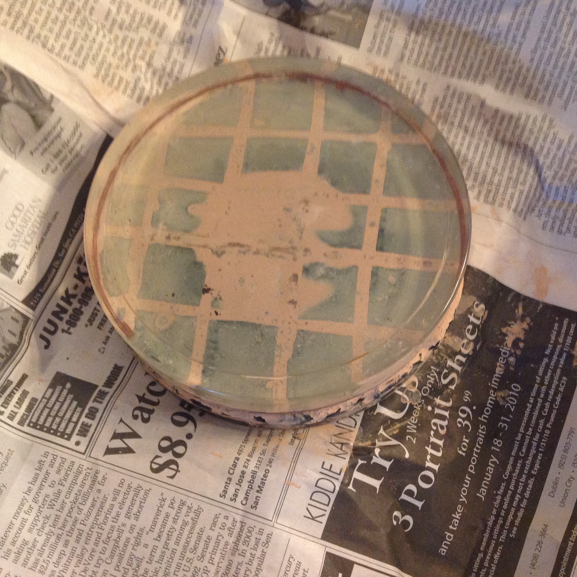
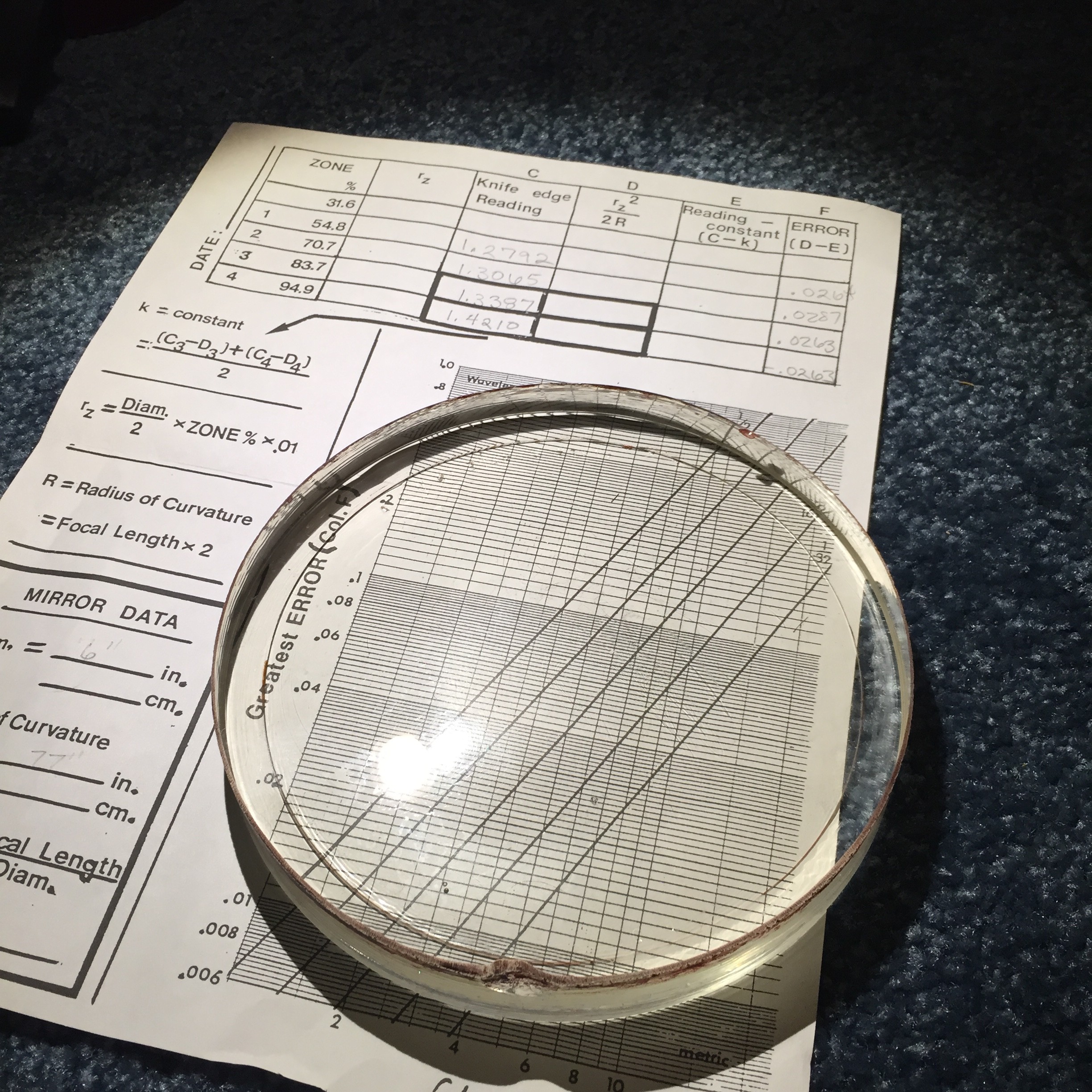
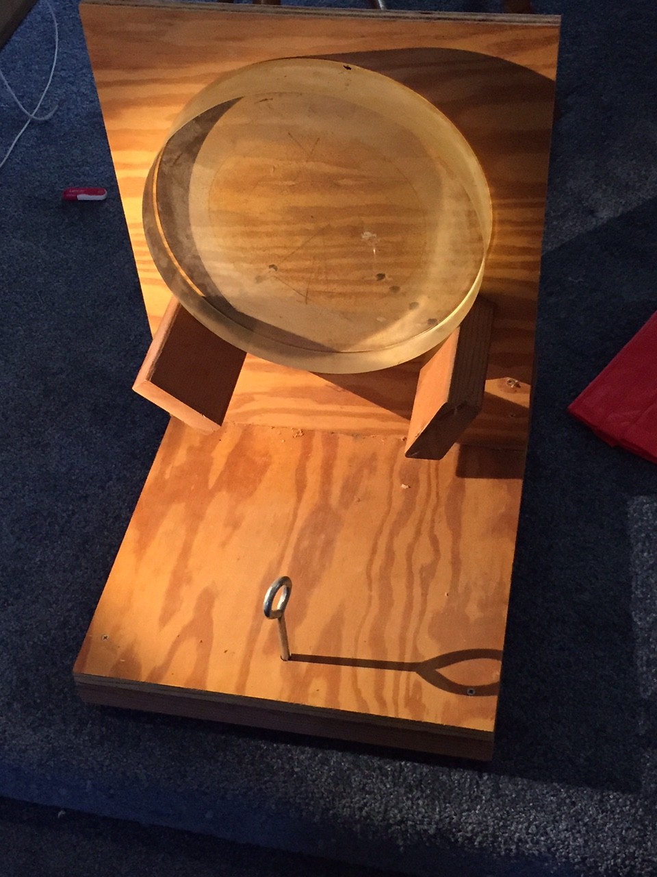
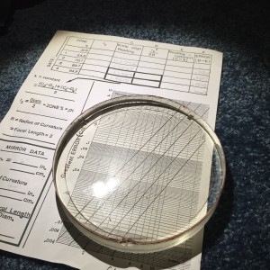
Including something I don’t recall: a polished 6″ mirror, along with a test sheet that was written in my hand writing. The mirror is an old style Pyrex blank (with “PYREX” embossed on the backside, and a bubble or two inside) with some staining of rouge around the outside. I have no recollection of this particular mirror, but I looked at the test sheet. It indicates that the radius of curvature was 77 inches (f/6.4) along with some measurements. I’ve no doubt that these measurements were made by my telescope making mentor, Paul Zurakowski.

Back in the day, we actually did a fairly crufty bit of data reduction, which I ultimately discarded as too crude to be really informative. We gathered good data, but our reduction was the kind of thing that you could do by hand (even though we used one of Paul’s aging Macintosh computers to do the calculation). I thought it might be good to dust off a program that I used to use and see how good the mirror really is.

Instead of using a Couder mask, Paul always used a pinstick: a ruler which had pins set at various places along the mirror. The idea is the same as the Couder mask: you worked to try to match the same intensity at the matching pins. Paul’s pinsticks were always set for five zones: 31.6%, 54.8%, 70.7%, 83.7% and 94.9% of the mirrors diameter. I tried to remember where these numbers came from. A moment’s playing revealed the secret. First of all, you begin by considering the number of zones, in our case, five. If you take a circle and divide it’s area into give equal parts of increasing area, you’ll basically have an inner most circle with area of the total area / 5, and then a series of donuts around, getting thinner and bigger as they go out to the end. (You can think of the innermost circle as being a donut with an inner radius of zero). Now, for each of the five zones, divide that area into two equal parts. I wrote a small snippet of python to do the math:

[sourcecode lang=”python”]
#!/usr/bin/env python

from math import *

D = 2

N = 5
a = pi * (D/2)**2 / N

inner_area = 0.

for z in range(N):
outer_area = inner_area + a
r1 = sqrt(inner_area / pi)
rm = sqrt((inner_area + outer_area) / (2 * pi))
r2 = sqrt(outer_area / pi)
print "%6.4f %6.4f %6.4f" % (r1, rm, r2)
inner_area = outer_area
[/sourcecode]

The output is a list of inner/middle/outer radii each zone. Since this run produces the values for a mirror of radius 1, you can read that the middle of each zone are the percentages that I listed above. You can change D to be the diameter of your mirror, and you’ll get the following values:


Inner Radius Average Radius Outer Radius
0.0000 0.9487 1.3416
1.3416 1.6432 1.8974
1.8974 2.1213 2.3238
2.3238 2.5100 2.6833
2.6833 2.8460 3.0000


To reduce the data, I downloaded the classic “Tex” program from the Stellafane website. It’s based upon the test derivation in Jean Texereau’s classic “How To Make A Telescope”, with a few changes. The authors are Michael Linder and Larry Phillips. I used the code that I wrote above to calculate inner and outer radii for each of the five zones, and then entered the data from my old test sheet. Paul’s tester used a metric micrometer, so all his results were in terms of centimeters, so I divided each test measurement by 2.54 to convert to inches. Additionally, we seldom tried to get the radii for the innermost zone: it’s often hard to judge, and a significant portion of it is covered by the secondary anyway, so we usually skipped it and just did four zonal measurements. The readings that I got were .5036, .5144, 0.5270, .5594 inches respectively. The resulting output:

	TEXEREAU MIRROR TEST SHEET

           Comments: Six   Optical diameter: 6
  Readings per zone: 1
Radius of curvature: 77
                f/D:  6.42
   Diffraction disc: 0.000169092

 1 ZONE                1          2          3          4      
 2 h(x)              1.8970     2.3240     2.6830     3.0000
 3 h(m)              1.6195     2.1105     2.5035     2.8415
 4 hm**2/R           0.0341     0.0578     0.0814     0.1049
 5 hm/4f             0.0105     0.0137     0.0163     0.0185
 6 D1                1.0072     1.0288     1.0540     1.1188
 7 D2                1.0072     1.0288     1.0540     1.1188
   D3                1.0072     1.0288     1.0540     1.1188
 8 D123              1.0072     1.0288     1.0540     1.1188
 9 D123 -  0.9946     0.0126     0.0342     0.0594     0.1242
10 Lamda c          -0.0214    -0.0236    -0.0220     0.0194
11 Lamda f * 1e5     -22.55     -32.38     -35.72      35.73
12 Lamda f / rho     -1.333     -1.915     -2.113      2.113
13 u * 1E6             5.86       8.41       9.28      -9.28
14 Wavefront           1.44       3.23       4.75       0.00
	Reference parabola: y = 1.00446 * x**2 + -1.809

Maximum wavefront error = 1 / 4.5 wave at zone 3

It predicts the wavefront error is about 1/4.5 waves: serviceable, but not outstanding. I’ll have to get this in front of the tester again this Friday to check it out some more. I suspect the test is probably roughly correct: I’ll expect to see a pretty good but not outstanding mirror. The Tex program isn’t as sophisticated as some of the more recent programs. First of all, the h(m) listed above is the middle of the zone (average of the inner and outer radii), not the radius of the pinsticks, although the difference is very small (.03″ at the inner zone, hard to see at 77″ away), and not likely to cause the results to shift much. More important is the handling of the “reference parabola”. I have to go back to Texereau to read about what this program does, but the basic idea is that if you choose a different reference parabola, you can often get lower peak to valley errors, and this is just equivalent to refocusing the telescope slightly. I suspect the mirror might fare a little better with this adjustment.

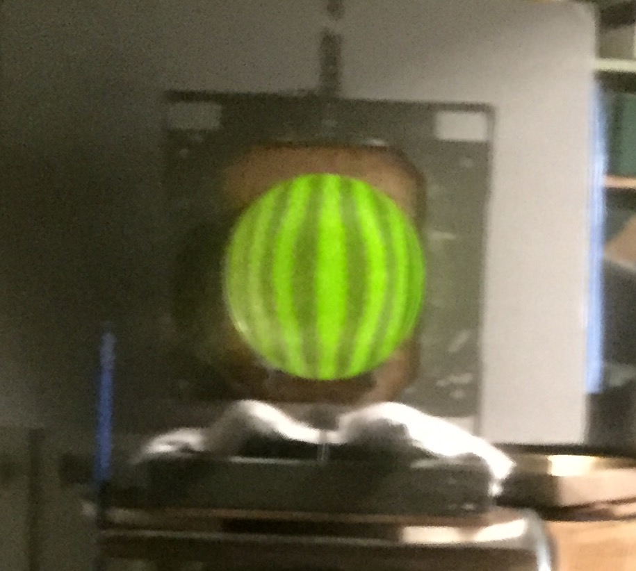
If anyone has access to any of the better programs, feel free to tell me what your program thinks of this mirror. I’ll try to get some photos of the Ronchi test, and look at the overall surface roughness and check it for a turned edge. Stay tuned.

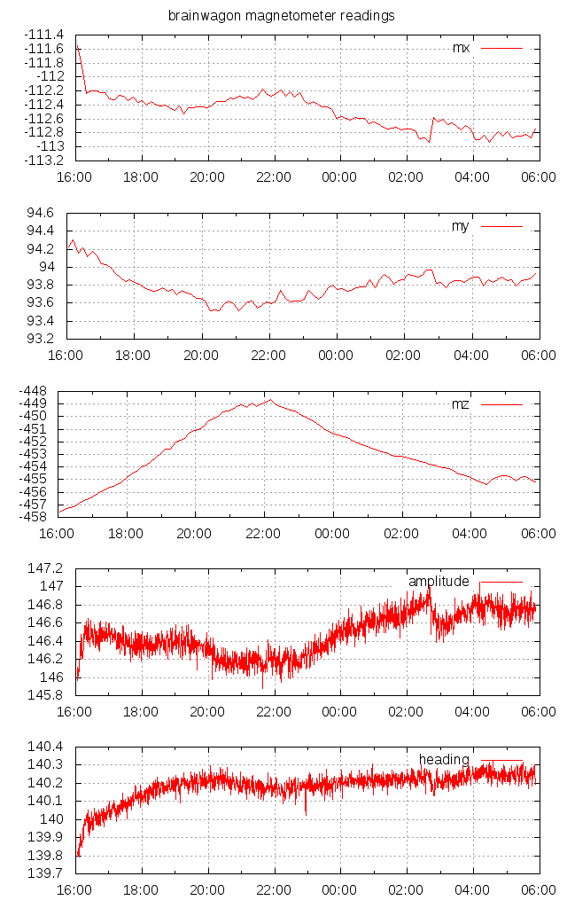
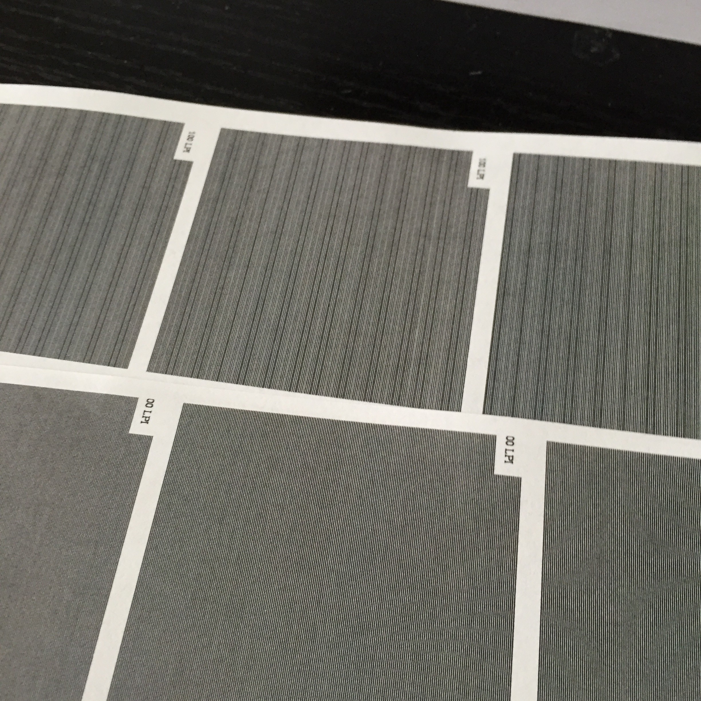
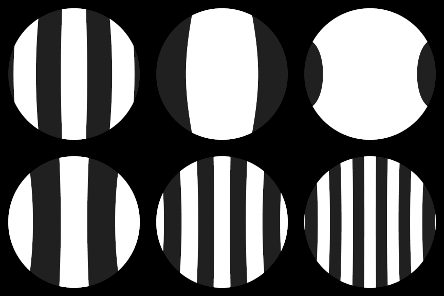
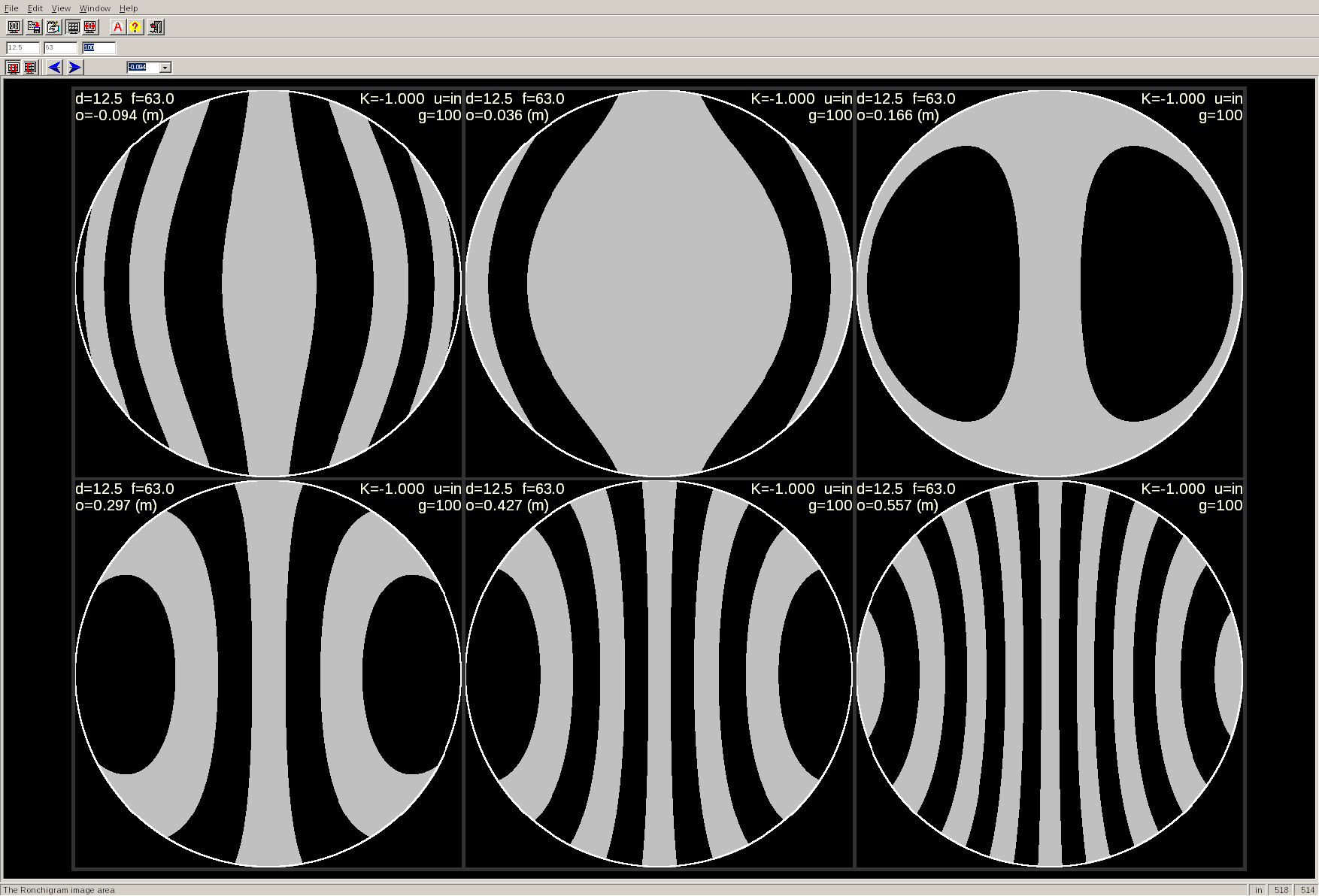
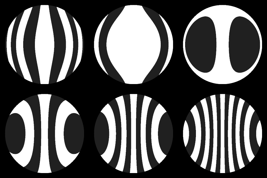
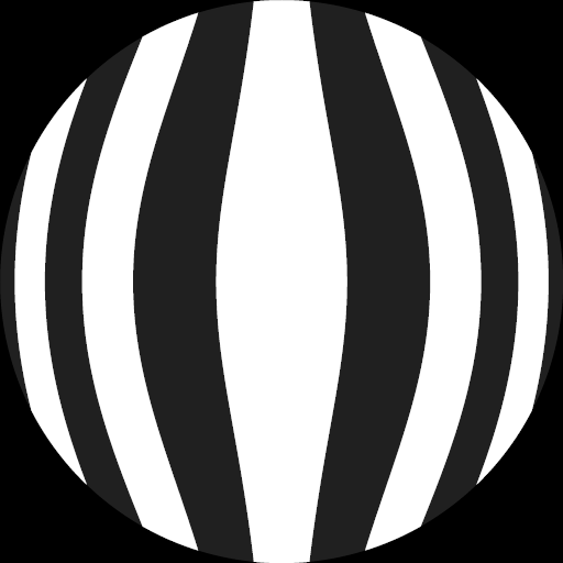
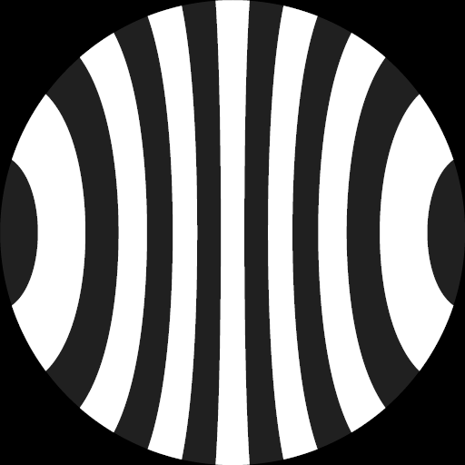
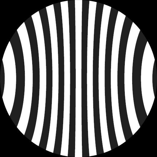
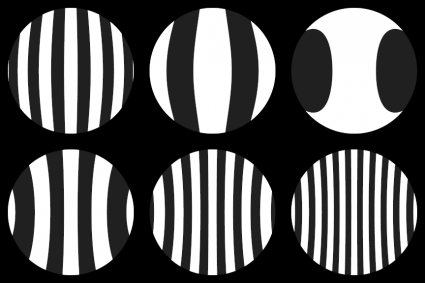
Addendum:: I thought it might be good to have a set of Ronchi patterns setup to compare against for my next testing session. Using the code I put on github, I did one for a 6″ paraboloid with a 100 lpi screen and the 38.5″ focal length.

test

Addendum2: Last night, I went back to my copy of Texereau, and read again how I should interpret this data. It will take a little bit more thought than I could muster to remember the exact details, but there are two bits to remember about this test. Quoting:

Danjon and Couder have pointed out that a good objective must satisfy a double condition:

  1. The radius of the circle of least aberration should be comparable with that of the theoretical diffraction disk, and on the average, the transverse aberrations should not exceed the diffraction disk radius.
  2. Maximum wavefront error must not exceed a quarter-wave, and for the major part of the mirror surface should be appreciably less.

Further down:

At the workshop of the Societe Astronomique, we release a mirror only when final values of ΛD / ρ are less than 1 and the wavefront error is less than 1/10 wavelength.

By the standards of Jean Texereau, this mirror is not ready for use. It doesn’t pass the 1/10th wave criteria, and the size of the circle of least aberration (which you can read along line 12 in the output above) is larger than one for all zones. I’ll have a look at it some more and do some more measurements, but I think I’ll be making a new pitch lap for it to finish it. I’m also pondering making a more up to date and portable version of Texereau’s program so that I can have it for use going forward.

Ronchi code now on github…

I updated my old 2001 Ronchi test code to support arbitrary conic surfaces, and then uploaded the code to github.

My current 12.5″ project is an f/5 paraboloid:

test

If we were interested in making a spherical mirror, we’d have these as patterns:

test

Why bother writing this code? I’m actually interested in trying to acquire images using something like the Raspberry Pi camera, and then generating a matching pattern via an image optimization process. Having this code might be useful.

Addendum: Somewhere tucked away I have a mirror I did for a 6″ f/12 mirror. I think that I never really did a proper Foucault test on it, because the focal length is so long, I think I just figured it to as good of a sphere as I could. I thought I’d use my code to see what it would look like with the same offsets using the Ronchi test. Here’s the resulting patterns:

test

As you can see, there is a small hint of correction, most visible just outside of focus. I’ll try to dig out the mirror for testing this Friday, as well as a 6″ f/5 chinese reflector I have, which I think is just a sphere. With any luck, I’ll also get a new pitch lap made for the 12.5″ mirror.

Checking my own Ronchi test code…

It was a long time since I wrote the code that I used for Ronchi code, and while I had some confidence in it, I wasn’t 100% sure that I had verified it. So, today, I took a copy of Ronchi for Windows 2 (I downloaded it from here) and set it up to predict the patterns for a 100 LPI screen and the 126″ radius of curvature that my current 12.5 mirror would have. I had it generate the patterns at six different offsets. Here’s the result:

ronchi for windows

I then took the same measurements and offsets, and added them to my own program and generated the similar array. Here are my results:

mytest

They look pretty much dead on. I can feel pretty confident about using my own code.

Addendum: This used to be more important to me, because I often didn’t have a Windows machine to run programs like Ronchi For Windows. In fact, I don’t have a box that runs Windows now. To write this article, I did confirm that using the Wine compatibility layer to run it on my Linux box, without the hassle of using a virtual machine or some such. Nifty.

Nifty telescope idea…

Since I stopped actively working on building telescopes, there have been numerous bits of technology that are now widely and cheaply available, and that can be used to implement new, interesting functionality. In particular I hadn’t considered that the same kind of sensors which are used to control quadcopters could be used to determine the position and orientation of a telescope tube. You could plunk the telescope down in any position, in any orientation, and it would be able to use the GPS, gyro, accelerometer and magnetometers to determine where the scope is, what time it is, and where it is pointed. While the overall accuracy might be a little low, it probably can point to within the low power field of a typical telescope.

I’m not the first to think of it. I got the idea from here.

I’ll leave this idea percolating in the back of my head. Worthy of experimentation.

Dusting off old Ronchi Testing Code…

At the Chabot Telescope Maker’s workshop, we make a lot of use of the Ronchi test. It’s great for figuring out gross defects and problems with your mirror. Back in the day, I wrote a simple program to generate Ronchi patterns for a given parabolic mirror. Here are six Ronchi patterns generated by my code for a 12.5″ mirror, with a radius of curvature of 126 inches (same as my mirror in progress) and a gratings with 100 lines per inch. The images are offset by -0.3, -0.1, .1, .3, and .5 inches respectively.

12a

12b

12c

12d

12e

12f

Not bad. But I can think of a few different things I can do with this code:

  • First, it should be able to generate pictures for other conic surfaces than paraboloids. Being able to specify the conic constant would enable you to see hyperboloids and oblate spheroids.
  • I never actually verified the results against reference implementations, or if I did, I don’t remember doing so.
  • I should be able to specify deformations like turned edge or shortened inner zones.

When I get this working, I’ll post the code.

Flying at Lime Ridge Open Space…

It was a warm and reasonably calm day, so Carmen and I decided to take the Phantom 2 out to Lime Ridge Open Space, where many RC enthusiasts fly. Rather than bore you with 18 minutes of video, I thought I might give you two short video highlights… Without further ado:

An Arduino Powered HF Beacon…

LB3RE sent me a link to this awesome HF beacon by Anthony, F4GOH and Christophe, F4GOJ that has many of the same features as my (as yet still in-progress) beacon transmitter does. And, of course, his actually exists, so it’s already infinitely more awesome than my idea.

I was particularly interested in his very simple power amplifier using 4 ganged BS170s. I’m likely to be operating mostly on 30m, so I think I could probably get buy with a single harmonic filter, and I am not imagining that I need all the relay switching, but there is some good information to be mined in there.

Gert’s 2015 Jupiter Campaign

I forgot to mention my chat with Gert, another telescope making regular up at the Chabot Telescope Maker’s Workshop. He’s a skilled astrophotographer and all around interesting guy, and has embarked on a campaign to do some high quality imaging of Jupiter. You can see some of his results here. Pretty nifty stuff. I copied (without permission, hope that’s okay Gert) one of his nicer images below as a tease, but you should surf over to his website for many more awesome results.

Jup_20150225_17_062334_ps2

He also suggested that this $300 webcam was especially well suited for astronomical images. Given his great results, I think I should pay attention to his recommendations.

Perhaps some time in the future I’ll get to doing some of this video/webcam astronomy.

Dusting off some old equipment…

If I am going to get going on this mirror again, I need to dust off and/or build some new test equipment. I never really did make an adequate Foucault/Ronchi tester, preferring to do all my testing at the workshop, but frankly, that seems a cowardly on my part. I suppose I’ll have to figure dummy one up. At it’s simplest, I really just need a light source (an LED, most likely dimmable) and a Ronchi grating. I also like the idea of setting up a small laser to serve as an alignment guide. That will probably be good enough to get started.

Then, I need to make some pitch laps. I think a full sized lap is probably a good idea, but I may want to make a smaller (8″ or even 6″) lap for figuring. I was getting pretty good at working subdiameter laps before I stopped, but I imagine I can get back to it quickly with a little project.

But one bit of old equipment that I have extracted from my garage is my mirror stand. Here it is with my 12.5″ mirror in place:

IMG_0198

Tomorrow I’ll spend some more time doing inventory on the parts and equipment I have. And maybe take the time to jury rig some Ronchi gratings.

Telescope Making: a new return to an old passion..

Even recent readers of this blog may not know of one of my old passions: building telescopes. Back when I was ten or eleven years old, I read an article in Popular Mechanics or some such that told how you could build a telescope from scratch, including grinding and polishing your own mirror (most amateurs build reflecting telescopes, where the primary optic is a mirror, rather than refracting telescopes which use lenses). Somehow, I conned my dad into beginning that as a project. We purchased a 6″ mirror kit from Edmund Scientific, and set to work.

Sadly, my dad was diagnosed with Hodgkin’s disease shortly after that, and passed away several years later. The telescope mirror sat unfinished in my mom’s closet for about fifteen years.

Until I moved to the SF Bay area in 1991, and learned of the Chabot Telescope Makers Workshop. They met up at the old Chabot Observatory every week, and under the leadership of mentor and friend Paul Zurakowski, hundreds of people learned about building and using telescope. I served as a volunteer instructor for a dozen or so years, helped hundreds of people on their projects, and did several of my own, until family commitments and such proved to be too much for me, and I stopped going, about five years ago.

And yet, I still am interested in it. Things are a bit smoother now than they were, so last night I decided to get up to the workshop and see what had changed. The answer is: not a heck of a lot. People are still showing up and building telescopes. A lot of the same people (Rich, Dave, Anthony, Mark, Alan) are showing up and carrying on in the same way they’ve been going on for years.

I brought in the project that I had going when I stopped: my 12.5″ f/5 telescope mirror. It was polished out, and I had begun figuring it, but it has sat on my shelf for more than five years untouched. I used the Ronchi tester that they have at the workshop to check out the general figure:

FullSizeRender

(Pardon the bad cell phone picture, but it conveys the right information). Most of you won’t understand what you are staring at, but even though I’ve been away from this for a long time, I can see that the figure is a bit rough, with a broad center zone which is a little bit “flat”, and the overall correction is a little bit overdone. I think it’s time to make a new lap and get working on this scope.

I’m not sure that I’m going to get up to the workshop every week like I used to, but I am going to try to get up their at least once a week, and to do a little bit of work on my telescope every week. I’m sure you’ll be reading more about it here. Stay tuned.