This post is the kind of round about post you get first thing in the morning. I’ll get to the title question at the end.
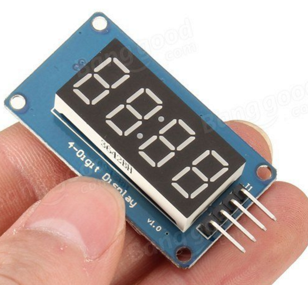
This morning, I was interested in doing a tiny bit of tinkering. I had found one of these 4 digit 7 segment LED displays while digging around for something else. You can get these modules for about $2.50 from banggood, and potentially for as little as a buck on eBay.
A little over a week ago, I was tinkering with a WeMOS D1 Mini board that I had acquired, and decided to port my Plan-13 library to it. Long (long long) time readers may remember some years ago that I wrote this code to predict the position of satellites, first in Python, but then ported it to C and had it running on the Arduino as part of my ANGST (Arduino ‘n Gameduino Satellite Tracker) project. But that project had a number of shortcomings:
- It was fairly complicated, and required a number of additional add-ons to work. I used the Gameduino to generate graphics, had an external RTC and EEPROM to store orbital data, and used an optical shaft encoder to move around. Yes, it was attractive and fun, but not cost effective.
- It had no easy way to update orbital elements. You had to connect it to a PC and reprogram it with new orbital elements each time you needed an update.
But these WeMOS boards are built around the ESP8266 modules, which have a number of advantages:
- They are based around an 80Mhz 32 bit processor, instead of a 16Mhz 8 bit processor.
- They have 4Mbytes of flash memory. You can easily configure some small part of that to serve as a miniature file system, ample to store orbital elements without any additional hardware.
- They are cheap: around $5.
- And most intriguingly: they have WiFi.
So, I worked on the spiritual descendent of ANGST. Using the platformio system I moved a copy of my Plan13 library to a new project, and started tinkering. As of now, the project:
- Wakes up and connects to my local WiFi network
- Establishes a connection to an NTP server, so I can get the time
- Connects to Celestrak and downloads the latest orbital elements for the ISS
- Predicts the next three passes from my home location
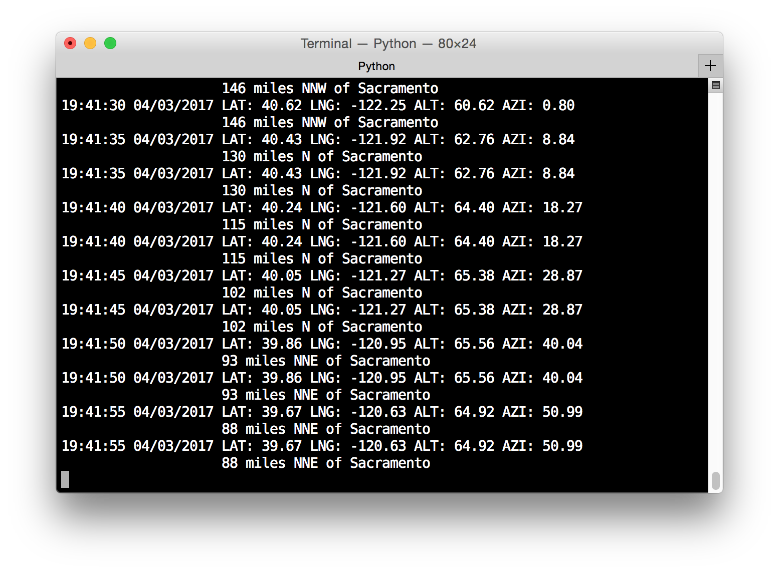
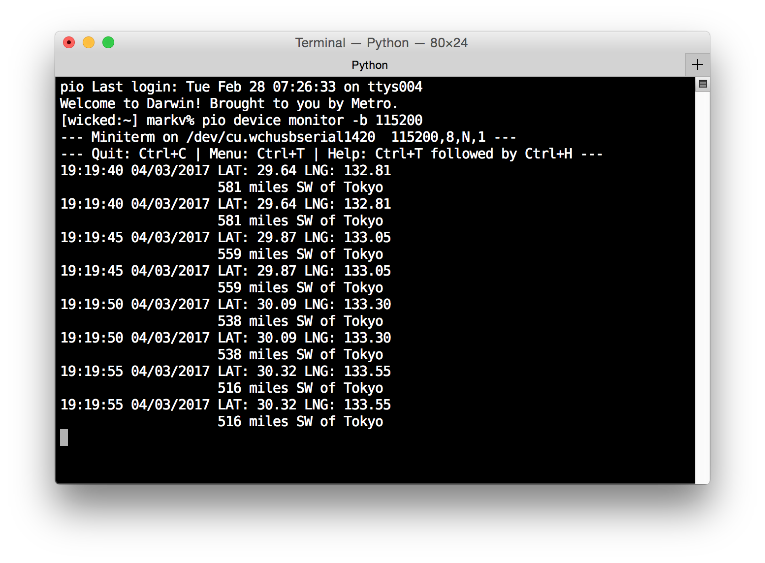
- And then enters a loop, predicting the sub-satellite latitude and longitude, its location relative to some major world cities, and if it is above the horizon, then the azimuth and altitude of the satellite.
Here is the current data as I write this:
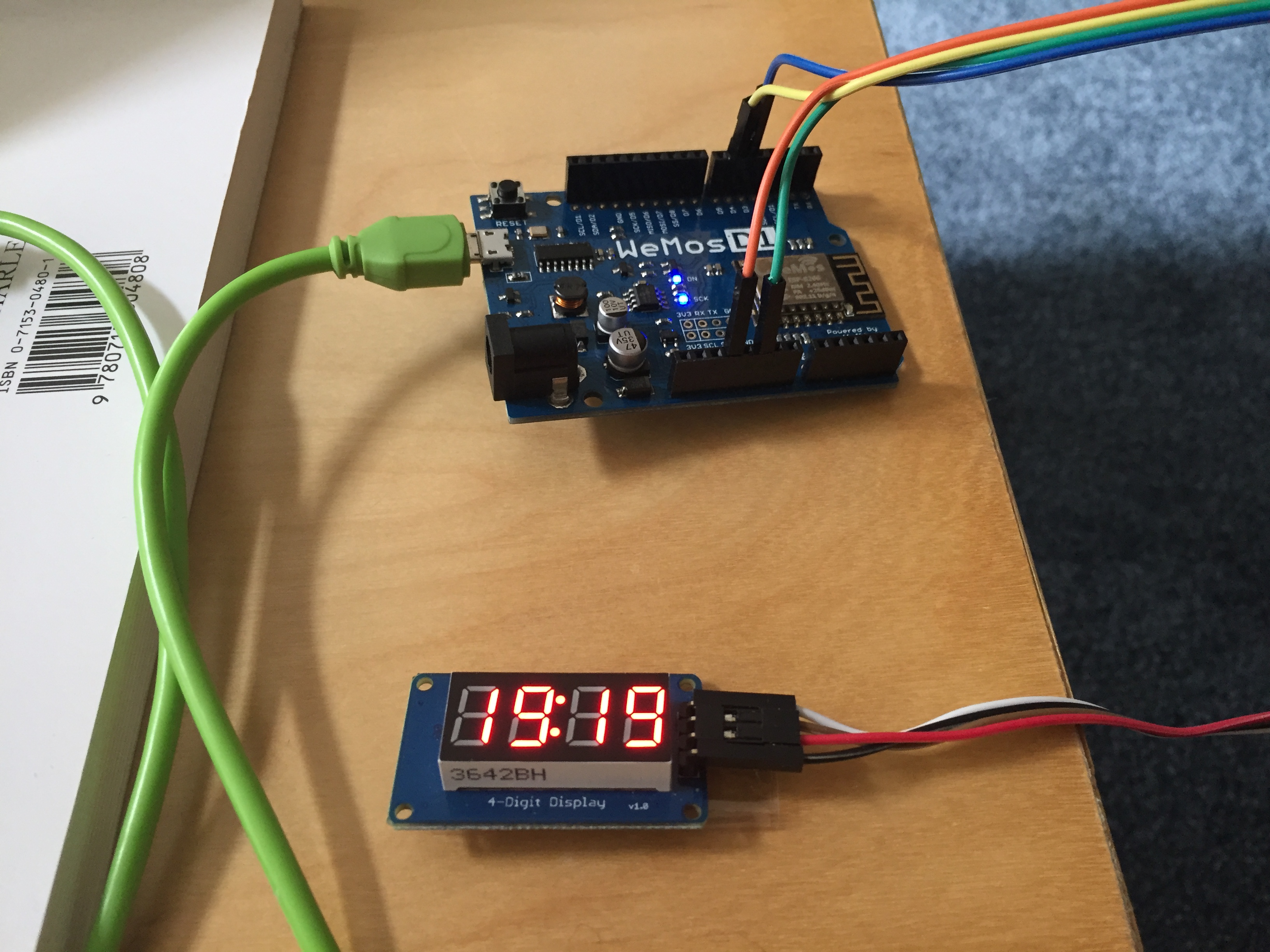
But the one thing it did not have until this morning was an external display. Hence, the TM1637, and a little tinkering.
Time is in GMT, but eventually I will also have it have the option of using local time (it is more convenient to use GMT for the satellite computations.)
To get this to work, I could have dusted off the work to drive the similar TM1640 based displays that I used in another project, but I thought that I’d use a standard library instead. The platformio system has a pretty nifty library manager, so I searched for a library, found one (cool!) and it claimed compatibility with the ESP8266. Neat.
So I read some of the example code, patched it to output the time in the main loop(), and tried it.
It didn’t work.
I double-checked connections.
It didn’t work.
I tried their example.
It didn’t work. The displays remained dark.
Grumble. I opened up the code and tried to see what was going on. It didn’t take me too long to figure out what was going on:
Here is a link to the code, and a screen grab of the offending lines:
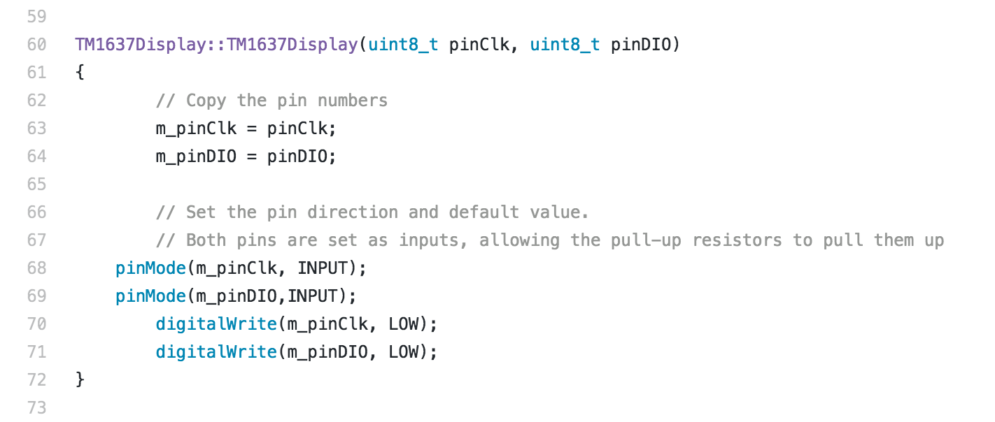
It’s not exactly my first rodeo, so I was immediately suspicious when I saw that the initializer set the mode for the two pins to INPUT, rather than OUTPUT, but then immediately wrote to them. That doesn’t seem right, does it?
Well, this isn’t even my second rodeo. I know that Arduino’s ATMega328 processor has internal pull up resistors, and I’ve seen odd code which used pinMode to swap back and forth between high and low, not using pinMode.
But the ESP8266 (thought I) doesn’t have internal pull ups. I’m pretty sure that’s true, but I never got to verify it, because all of a sudden, with no change whatsoever, my program started working.
I hate it when that happens.
It’s been that kind of a week.
But it made me think about how this works. Here is my guess, and I’d appreciate corrections.
During initialization, it sets pinMode to INPUT, and writes a LOW value to the data pin. Even though we’ve written a LOW, the pin is pulled HIGH by the action of the (external) pull up resistor.
When the driver wishes to shift the output pin to LOW, it uses pinMode() to shift the type for the pin to OUTPUT. When it wants it to be high, it sets pinMode() to INPUT.
I find this odd in a couple of ways:
- It is not any shorter or more efficient than using digitalWrite.
- It is certainly no clearer.
Is there something I’m missing about why you would code this stuff this way?
Of course, I wouldn’t have dug into this code at all had I not had a mysterious (and fleeting) failure at the beginning, so I am not sure how it really matters.
Addendum: While I was typing this, the ISS did a 65 degree elevation pass which was captured thusly. I only then noticed that it was producing duplicate messages for each five second message. Must have goofed when I installed the code to blink the clock’s “colon” segments. I’ll get it sorted later.