Monthly Archives: January 2018

More progress on the ISS clock project…

I haven’t posted an update here recently, but I am (mostly) living up to my New Year’s resolution to spend at least 30 minutes a day working on a project. This has taken the form of some stupid but necessary chores (like fixing the broken pull cord on my lawnmower) but has mostly taken the form of additional incremental additions and improvements to my ISS clock project. This has mostly taken the form of noting a small deficiency, and then working until that deficiency is ameliorated.

The ESP32/Arduino environment still has access to the FreeRTOS operating system below to create tasks, semaphores and queues. I decided that I would implement the program as a set of tasks of different priorities. One task’s job is to compute the current latitude, longitude, altitude and azimuth for the satellite. Another lower priority task scans forward in time, and finds the next time when the satellite rises and sets. When it finds those, it pauses until the current time is beyond the found set time, and then continues searching for the next rise/set pair. The final task runs the display, showing all the current information. If the time of the next satellite rise time (or AOS — Acquisition of Signal) is set, then the display process will give a countdown in hours/minutes/seconds.

This was all working reasonably well, except that I noticed that the time display would frequently “jump” a second, skipping from 42 seconds to 40 seconds in countdown, and sometimes even in the clock display jumping from 10 to 12 seconds for example. I didn’t think any critical path in the code would account for anywhere near that amount of delay in switching between processes, but tried reorganizing the code in various ways to be sure.

In the end, I realized that it had nothing to do with multitasking or the like. I had written code in two different places to convert an internal representation of time used by my Plan 13 satellite library into H:M:S format, and had committed the same error in both locations.

The thing that I realized is that unlike normal Unix time calls, internally my code represents the current time of day as a double which represents fraction of a day. To step the time forward by one hour, I increment that value by 1/24. I have a function whose purpose is to convert this internal representation separate hours, minutes, and seconds.

Here is a (slightly edited) version of my original code.

[sourcecode lang=”cpp”]
void
DateTime::gettime(int &h, int &m, double &s)
{
double t = TN ; // TN is the time in fractions of a day
t *= 24. ;
h = (int) t ;
t -= h ;
t *= 60 ;
m = (int) t ;
t -= m ;
t *= 60 ;
s = t ;
}
[/sourcecode]

The problem appears to be rounding interacting with the timing of the display process. Staring at this code, I’m not sure what I was thinking. I rewrote this code in the following way:

[sourcecode lang=”cpp”]
void
DateTime::gettime(int &h, int &m, double &s)
{
double t = TN ; // TN is the time in fractions of a day
int ts = (int) round(t * 24. * 60. * 60.) ;
s = ts % 60 ;
ts /= 60 ;
m = ts % 60 ;
ts /= 60 ;
h = ts % 24 ;
}
[/sourcecode]

This code works much better. I had coded a similar routine in new code which had the same error. I must admit that I’m still a little fuzzy about how the timing of the display process interacts with this rounding issue to introduce the errors that I observed, but I suspect it has to do with the fact that I inserted delays in the display process to keep that process from updating somewhere around two times a second. I think that the prediction task (which runs for about twenty seconds usually) may be starving the low priority display task just often enough to cause the rounding error to manifest.

I’ll ponder it more later.

Things that are now percolating to the top of my todo list are to understand the event handling of the NtpClientLib library. Occasionally it will toss errors from the WiFiUdp.cpp file, and error handling is not appropriate (sometimes it doesn’t set time properly). I suspect I’ll have to dig into the networking code in the library a bit deeper.

Addendum: The display on this thing is one of those tiny 0.91″ OLED displays. It’s really at the limits of what I can comfortably read, and I’d like to have more space (and potentially color). I have some small 1.8″ LCD boards, but I stumbled across the M5Stack board which appears to be available on banggood.com. It looks like a cool little box.

I ordered it from this link on banggood for about $33. Besides having an ESP32 module, it includes a case, a 320×240 2″ color LCD panel, and three buttons. The larger display size and buttons are a great fit for my ISS project. When it arrives, I’ll quickly work on a port of this code to that.

If that doesn’t work, I’ll probably work on adapting it to some of the ST7735 modules I have lying around that I ordered from icstation.com.

Stay tuned for more progress, and eventually links to the git repository for the code when I am not embarrassed by the code.

Brief Update on my ESP32 ISS Clock

Several days ago, I cobbled together a short bit of code to make an NTP enabled clock out of an ESP32/OLED module. I had previously used an ESP8266 and a separate module to make a little demo that predicted the location of the ISS. I thought that the ESP32 would make a better development platform, for a number of reasons:

  • It’s faster.
  • It is dual core.
  • It includes a small real time operating system that allows you to create communicating tasks.

My early example didn’t make any use of that, it was just a clock. So today I spent a little more than an hour to expand the basic code outline to include some new features:

  • It now links in my C++ library that implements the Plan 13 algorithm for doing satellite prediction.
  • The previous NTPClient library wasn’t really very good: it didn’t include any way of accessing day/month/year. I switched it to use NTPClientLibinstead, which is much better.
  • I experimented with using the xTaskCreate call to create different tasks, one of who updates the current satellite position, and the other which updates the display. This proved to not be difficult and works remarkably well. I anticipate that this will make my final version of the code easier to write. I can implement one process whose job it is to scan forward in time, looking for the next satellite pass. When it finds one, it can use a queue to send it to the display task, and can continue. This makes the program easier to write and more modular.
  • I also did some work to fetch orbital elements directly from celestrak.com so that the display will always be up to date.

The code is not in a state to share yet but I think it is going to be pretty neat when I’m done. The gadget could easily be mounted in a small case and carried into the field, where it could be entirely battery powered.

Stay tuned for updates.

A short audio book review: The Making of the Atomic Bomb, by Richard Rhodes

I often get nearly an hour and a half of commute time in my car each day, so I have lots of time. Rather than just waste it, I like to listen to podcasts or audio books. Recently I decided to subscribe to Audible, and started getting some interesting books.

I had read The Making of the Atomic Bomb by Richard Rhodes years ago, but decided to listen to it again. I was particularly interested in it from a scientific viewpoint: how a nearly complete lack of knowledge about the internal structure of the atom at the start of the 20th century had in the span of just a few decades progressed to the unleashing of an atomic weapon at Trinity, and then used in war just a month later at Hiroshima and Nagasaki.

Rhodes won the Pulitzer Prize for this book when it was first published, and listening to it again, it’s not hard to see why. It carefully spans the development of the science of physics with a balanced mix of personal, political and scientific information. It is the kind of book that I really like: dense and full of detail. Ultimately, it tells the broad arc of how physicists began to unravel the internals of the atom, and how the growing realization of the possibilities of nuclear energy were sculpted by both their internal philosophy and the political climate of the time. Men with deeply pacifistic beliefs ultimately joined a huge effort to create a weapon of unimaginable power, sometimes entertaining the notion that such a weapon was so horrible that it might end warfare entirely, and others just pragmatically trying to ensure that the Nazis and the Japanese didn’t get their first.

I think this is where the book is perhaps most interesting. If Rhodes has a view on the ultimate morality of dropping Little Boy and Fat Man on Japan, he doesn’t really let the reader know what it might be. I think in a way that might be the only really satisfactory way of dealing with the deep moral questions that atomic weapons brought into the world. Rhodes reports what happens without the editorializing that plagues other works, and that leaves the reader space to develop his own opinions.

Ultimately, that is the source of my worst but still mild criticism of the work. It is 27 chapters long, and the last two deal with Hiroshima and Nagasaki. The aftermath of Hiroshima is described in a way that is different than the other events. It consists mostly of the eyewitness testimony of anonymous survivors. It’s tough stuff, and as you can imagine, more visceral and emotional than the rather academic tone that most of the rest of the book takes. Nagasaki treated rather briefly, mostly with just the observation that damage and deaths in Nagasaki were more limited because of the more rugged and varied terrain.

And then… the book is over. I don’t have my original copy, but I’m told that the original had a chapter dealing with the run up to the thermonuclear or hydrogen bomb, which Rhodes talks about in his book Dark Sun (which I have not read.) But it’s kind of an abrupt ending. I suspect that after I recover from the emotional gut punch of reading about Hiroshima, I’ll eventually get around to listening to Dark Sun.

Addendum: I should also put in a plug for James Mahaffey’s book Atomic Adventures. It was actually this book that reminded me of Rhodes’ book. It was on sale on Audible a while ago for something like $5, and I really enjoyed it. It tells a bunch of tales surrounding nuclear physics, including the development of nuclear rocket engines, nuclear aircraft, and the author’s onw flirtation with cold fusion. It is mostly a collection of disjoint stories, but told well and giving me an insight into many developments around nuclear physics that I heard before. Still scary and dire at times, but more manageable than The Making of the Atomic Bomb.

Other weekend projects, including a new cat tree!

I had a bunch of chores that I wanted to get done this weekend. Our gardener has disappeared off the face of the earth, and our front yard was looking ragged and weedy, so I decided to try to mow it myself. I have two mowers in my garage, a Black and Decker rechargeable electric that is approaching 20 years old, and a Toro gas mower that I hadn’t run in a couple of years. I hoped that a quick recharge of the electric mower would make it work, because I didn’t relish pull starting the other mower, but alas, it was not to be. A full night’s recharge didn’t seem to bring it back to life. Sometime when I’m motivated, I’ll have to pull the battery and give it a test. So, it was the Toro. Sadly, my arm is not in the greatest shape since my back injury, and since the mower hadn’t been started in quite some time, I thought it would be difficult.

It was.

I had to yank on the pull starter for a good five minutes before it caught once, and ejected a huge cloud of blue smoke, and promptly died again. Normally after starting to run a little bit, it would be easier to pull start, but that proved not to be the case. I had to flail away on that thing for another five minutes before it caught, ran rough and died. Another five minutes and it caught again, and died. But this time I managed to get it started. I let it idle for about five minutes, then quickly mowed my yard with the cutting height set fairly high. I then let the engine die, lowered the height and then pull started. It started, but also the cord snapped and I was left with the handle and cord in my hand.

Sigh. I finished my yard, but I’ll need to fix that before I can do it again.

I also pruned a hedge and took down Christmas lights.

On Sunday, I had a different chore. My cats had discovered how much fun it was to play in the limbs of our artificial Christmas tree, and they seemed genuinely sad when we took it down. I decided that they needed another cat tree to replace it, so last Wednesday I ordered this new cat tree from chewy.com. I started to assemble it this morning. Any misgivings I had about whether they would like it were immediately dispelled. Pepper was using the first scratching post before I even got to the next level, had explored the little cubby hole even before I got the screws in, and both were on top of every layer as I worked.

They seemed to like it.

I didn’t get to my 3D printer repairs.

Quick tinkering of an NTP clock with the ESP32

I spent a little time today trying to make the bare minimum code necessary for the ESP32 to connect to my WiFi network and synchronizing the time using NTP. It’s not really that amazing, but required a tiny bit of snooping around to figure out how to make it work. Archived here, just for fun.

[source lang=”cpp”]
/*
* tinkering a basic wifi shell/framework together
* duplicating work that I had done for the esp8266
* but which doesn’t appear to work on the ESP32.
*/

#include <NTPClient.h>
#include <WiFi.h>
#include <WiFiUdp.h>
#include <Wire.h>
#include <SSD1306.h>

SSD1306 display(0x3c, 5, 4);

const char *ssid = "**********" ;
const char *pass = "**********" ;

const char *ntp_server = "0.us.pool.ntp.org" ;

WiFiUDP ntpUDP ;
NTPClient timeClient(ntpUDP, ntp_server, -8*60*60, 5*60*1000) ;

void
wifievent(WiFiEvent_t event)
{
switch (event) {
case SYSTEM_EVENT_STA_GOT_IP:
Serial.println() ;
Serial.print("CONNECTED ") ;
Serial.println(WiFi.localIP()) ;
Serial.println("CONTACTING NTP SERVER") ;
timeClient.begin() ;
timeClient.update() ;
break ;
case SYSTEM_EVENT_STA_DISCONNECTED:
Serial.println("DISCONNECTED") ;
break ;
}
}

void
setup()
{
Serial.begin(115200) ;
delay(500) ;
Serial.println("ESP32 harness.") ;

WiFi.disconnect(true) ;

WiFi.onEvent(wifievent) ;

WiFi.begin(ssid, pass) ;
Serial.println("CONNECTING") ;

display.init() ;
display.setFont(ArialMT_Plain_24);
}

void
loop()
{
delay(1000) ;

Serial.print(‘.’) ;

display.clear() ;
display.setTextAlignment(TEXT_ALIGN_CENTER_BOTH);
display.drawString(64, 32, String(timeClient.getFormattedTime())) ;
display.display() ;
}
[/source]

Addendum: Here’s a quick video of it working, with a small extension to display the NTP address of the clock too.

A few quick thoughts on the Inky pHAT

Okay, I got it working. See!

But I had a number of really annoying problems, none of which really had to do with the hardware:

  • I installed it on a Pi3 I had lying around that previously had been running my 3D printer using Octopi. I tried to do an “apt-get update” and “apt-get upgrade” so I could install the python modules, but it complained with some obscure error messages. Since I had a fresh img file of a more recent version of raspbian, I thought I’d just ignore the problem and shift to that.
  • But, of course the computer gods hated me yesterday. It took a couple of tries for me to decide on using the latest Debian Stretch based distribution. I used the “lite” version without any desktop because, well, I could.
  • I still had trouble doing an “apt-get upgrade”. For some reason, I couldn’t reach “mirrors.ocf.berkeley.edu”. I suspected something to do with nameservers, but couldn’t really track it down. I eventually hardcoded a different server into my /etc/apt/sources.list, and got it to update.
  • I then had to install python-dev, which took a very long time, mostly because numpy takes forever to install.
  • I then installed python-pip, without incident, and did a “pip install inky-phat”. That gave me an error while installing “Pillow”, caused by a missing dependency for libjpeg. I eventually figured I needed a “sudo apt-get install libjpeg-dev” and then reran the pip command.
  • Then, for fun I cloned the git repository for the library so I would know where the examples are (after installing git of course) and then I could finally run their example code.
  • Oh, except you need to run “raspi-config” to enable the SPI driver, or it won’t work.

Phew. All in all, a pretty frustrating time, but in the end it works well.

A couple of more comments.

When it was shipped to me, the “white” of the display seemed pretty yellow and not very pleasing, but after running the demo program, it refreshed pretty well, and the whites (while not exactly brilliant) are much better.

As you can tell by the picture above, the image remains visible even when power is completely disconnected which is kind of cool. But the reality is that the Pi is pretty slow to cold start and draws a lot of power, so having a low power display on the Pi isn’t actually as interesting as a similar display would be on a lower power board like the ESP32. But that being said, I really like the display.

I mounted it on Pi 3. The board has a 40 pin female header pack (2×20) on the back, which mates with the pins of the Pi3. If you have a Pi Zero W, you’ll probably need to solder a bunch of male pins on the board to mate up with it.

The case that I have for the Pi3 isn’t well suited for the combination, and won’t close. I might have to design and 3d print something.

I’ll try to write some code for it shortly.

Inky pHAT arrives: a 3 color E-ink display for the Raspberry Pi

For some reason, I’ve always been attracted to E ink displays. They combine a number of interesting features like low power (none when not being refreshed), high contrast and a wide viewing angle. But they only recently have begun to get cheap enough to play with. The other day I was surfing around and discovered the Inky Phat from Pimoroni. Which is a cute little 212×104 display which has three colors (black, white and red). It was about $25, and interfaces directly with the Raspberry Pi. It’s basically the same size as a Pi Zero W, but can also be used on any other Pi with the standard 40 pin Pi connector.

I haven’t done anything with it yet, but it’s calling to me, telling me to rush home and give it a whirl. I haven’t got a project in mind for it, but it comes with a Python library to drive it, which suggests that it might serve as a good display for a small satellite tracker using my Plan 13 library.

I’ll try to get a short demo video of it up tonight.

Interactive Programming… in C

I’ve been kind of interested in a type of “livecoding” where changes to a code base are immediately reflected in a running program. I’ve seen Inigo Quilez (author of the famed shadertoy.com) do this with a scaffold that he wrote using OpenGL. Literally as he types new shader code, the changed shader is loaded and executed, and the new graphic image forms the background of his editor.

You can see an example of this here:

I started working on a similar framework, and got the basics working (except that I didn’t write my own editor, but merely ran vi in a window and updated the fragment shaders running in a separate window) but today I discovered this kind of cool idea: doing the same sort of thing in C.

Chris Wellons wrote on his blog back in 2014 about a set of techniques that could be used to do the same sort of interactive stuff in C.  The basic idea is to write a framework which constantly monitors a shared library, and when it is updated, reloads the library.  If it is not, then it calls an “update” loop.  I don’t think this is helpful for all sorts of programs, and there are a few details to be sorted, but it’s kind of cool.  I can imagine giving this a try on one or two projects that I’ve been pondering.  Archived for future reference.


Addendum: David Parrot posted this to my twitter feed:

In case twitter integration fails, it’s a link to Casey Muratori’s Homemade Hero on instantaneous live coding. I haven’t had a lot of time to watch the videos yet, but they seem very cool.

Yes, I crochet (and knit, although less well.)

In addition to my geek hobbies, I have resurrected a skill that was taught to me by my Grandma Busch when I was seven years old: crochet.

It began earlier in 2017, when Carmen wanted me a pussy hat so we could attend various protests and rallies. I told her I could knit or crochet one. I hadn’t done any of either since I was in my early teens, but with the Internet at my disposal, I was sure I could recover my skills. My first knitted attempt was pretty terrible (I was always better at crochet), but my second attempt in crochet was entirely respectable. I made myself a matching one, and also did one in camouflage colors:

After this, I kind of got the bug and decided to make Carmen an afghan. I found this excellent Bernat Blanket Yarn, and tinkered this together in my spare time over a few weeks. Carmen really loves it. It’s warm and snuggly, but with lots of air gaps that make it breath (and which the kittens like):

Speaking of cats, I made some cat toys stuff with catnip:

I also learned about a new technique called “planned pooling.” You take a yarn which is variegated, and by carefully spacing your stitches, end up with interesting argyle patterns. I haven’t finished a real project with this yet, but it’s pretty cool.

And of course I made some stockings for my grand daughters:

It’s all been a blast. I continue to tinker on projects: I have another afghan that I’ve stalled on, and have recently thought about doing a project with “c2c” (cornet to corner) crochet, as well as honing my skills with Tunisian crochet. I find this to be a good way to relax which uses a different part of my brain than programming.

Some links for those interested:
C2C (cornet to corner) crochet for beginners.
A quick guide from Red Heart on color pooling.
Getting started with Tunisian crochet

It can’t all be electronics and 3d printing after all.

Connector resistance matters: the Anet A8 PCB heated bed…

My previous entry talked about the problems that I’ve been having with the Anet A8. I haven’t had the time to actually do some rework of the connector (I should get to that later today) but while I was commuting I thought about it a bit, and was trying to answer the following questions.

  • How much resistance would this bad connection need to add to affect the bed heating?
  • How much power was being dissipated by the PCB and at the location of the bad joint?
  • Was there a significant danger of a serious meltdown?

The way I approached this was to first get some data about the heated bed. Nominally, the bed is rated for 12V at 1.2 ohms resistance. Using Ohm’s law, we know that the current is voltage divided by resistance, so the total current draw should be 10 amps, and the power is current times voltage, so the power should be 120 watts.

If you look at the bed, you’ll see it consists entirely of a very long, thin, wide PCB track which winds around the 220x220mm surface. It dissipates the power as heat, and since the resistance of the track is (very nearly) uniform, you would expect the total power to be dissipated across the entire length of the track, providing relatively uniform and modest heating.

We can model this system as a simple voltage source as 12v DC, with a series load resistance of 1.2 ohms.

If we have a bad resistive connection to the heated bed, we have some additional resistance in series with our load resistance. The total current through the bed drops because the resistance is now the sum of the connector and load resistance, which means that the total power drops. (We will imagine that the supply will continue to provide 12v regulated for this experiment.) The total power is divided between the power dissipated by the bad connector and the heated bed. A little work with Ohm’s law and voltage dividers, and you can figure out how that power splits depending on the connector resistance. I could go through the math, but it’s basic intro DC stuff. I wrote a little scrap of Python and made a graph as I varied the connector resistance
through some low values.

You can see that at even pretty small resistances, the power to the heated bed starts to drop significantly. More than that though, the power dissipated by the connector grows pretty quickly. It actually reaches its peak when its resistance matches that of the bed, where the green and blue lines cross, indicating that the power dissipated by the bed and pcb are equal, and dissipate 30 watts each.

But from a practical standpoint it is important to remember that while the 30w of the bed is spread along its entire (and substantial length) the 30w dissipated by the connector is quite small, and thus there is likely to be significant (or even catastrophic) heating at the connector. It is also important to note that as the connector resistance grows beyond this point, the power curve drops slowly, so it might continue to heat significantly over a much larger range of resistance values.

So, my math indicates that I should really be concerned about connector resistance. I think this means that I am going to avoid using a connector entirely, and solder 12 AWG wire directly to the power terminals, and carefully measure the total resistance before and after. I will also provide some additional strain relief so that as the wire flexes, it doesn’t work the joint loose.

That’s the theory. Stay tuned for the rework.

Debugging my Anet A8 hot bed…

As in most things, whether you achieve success has a lot to do with what connections you have. And this is true of my somewhat unreliable Anet A8 3D printer more than most.

My printer had been down for a month while I worked on getting a new hot end installed properly. It wasn’t so much that it was difficult, but that it simply took time to get the new parts, find an appropriate crimping tool for the thermistor, and install the new head. Mind you, reassembling the MK8 seems to be more difficult than you would think, but I am getting better at it.

I have been thinking of doing a hot end replacement to a new Bowden extruder, so I thought that while the iron was hot (so to speak) I would print the necessary brackets so I would have them on hand when I felt like that kind of tinkering. I got the stepper motor bracket printed, and was printing the necessary bracket to mount on the X-axis when I had the print fail because of a THERMAL RUNAWAY error message. A bit of debugging revealed that there was a problem not with the hot end, but with the heated bed. In particular, it seemed like it was unable to come to temperature. The controller basically jammed the current on full blast, but it seemed to stabilize at around 38 degrees Celsius instead of the desired 50 degrees.

That was where I left it a week ago.

Finally today I decided to disassemble the hot bed and see what the issue is. My suspicion was that as with the hot end, a thermistor had failed (or perhaps just become dislodged) and was no longer reading properly. I thought I’d remove the hot bed so I could examine the underside so I could see if there was any obvious problem. To remove the hot bed, you pull the four leveling bolts at the four corners, and disconnect the connector.

Looking on the underside, you can see the connector has six pins. There are two positive, two negative and two pins which go to the thermistor. You can order replacements fairly easily, for $13-$20.

But back to my broken hot bed.

Like 99% of all problems, it was pretty obvious once I looked. Here is a picture of this connector:

It may not be obvious in this picture, but the left most pin (wired to positive) is pretty oxidized and gray. Looking at the corresponding socket on the plug, it also appears oxidized and gray.

Normally, the resistance of the hot bed is supposed to be around 1.2 ohms. At 12V, that means that the bed should draw 10 amps and therefore about 120w. But if the connector adds just one more ohm of resistance, it basically halves the available power, and the bed may not heat very effectively. That’s what I’m thinking of doing.

Apparently these connectors do fail fairly often because they aren’t really rated for as much current as is passing through them, and they also aren’t really designed for a connection which flexes. I think what I’m going to do is remove the connector entirely and solder the wires directly to the pins. I’ll probably have to wait until this weekend.

3DPrint Wiki on replacing the Hot Bed connector

I might also take the time to do the MOSFET upgrade that people recommend for additional safety.

Link

If I was going to port my ISS code to the ESP32 using the ESP-IDF framework, I’d need a driver for the SSD1306 OLED display.  It does seem like some people have been down this path before.  I haven’t tried any of the following, but a little quick googling revealed some promising links:

https://github.com/yanbe/ssd1306-esp-idf-i2c
https://github.com/imxieyi/esp32-i2c-ssd1306-oled
https://github.com/nkolban/esp32-snippets/tree/master/hardware/displays/U8G2

The last is perhaps most interesting, as the UG8 library is commonly used in Arduino sketches.

The ESP32 vs. the ESP8266

Over the last year I’ve spent a small amount of money and a larger amount of time accumulating a bunch of development modules from banggood. This began mostly with me getting some spare Arduino modules cheaply. Whereas an official Arduino might cost you $25 or so from Adafruit or Sparkfun, you can get a Geekcreit clone of the same board for about $4 including shipping from China.

But you can import some other fun things besides Arduino.

A year and a half ago, I had received my first ESP8266 boards based upon the Arduino form factor. These would cool boards, based upon the ESP8266 wireless module from Espressif. The cool thing about these boards is that you can use the Arduino environment that you might already be familiar with to program, but the controllers themselves are significantly more powerful, and include wireless access. I have a few of these Arduino formfactor boards around, but they turned out to be less helpful than I would like, as the pin outs are moderately different and few shields are compatible. So instead, I’ve accumulated a fair number of ESP8266 boards which are based upon the format called “Wemos D1 Mini”:

The Wemos D1 Mini

I’ve been having a lot of fun with these.

But in the last year, Espressif has started shipping a new chip, the ESP32, which has a number of cool new features, but which most notably include Bluetooth Low Energy (BLE) and a dual core processor. At first, these chips were fairly hard to get, and modestly more expensive, but now the pipelines appear to be full, and the necessary software support is in a pretty good state.

Banggood carries a good basic module for just $7.

And, you can get a module with an OLED module premounted for about $11.

I’ve had these ESP32 modules lying around for a while and haven’t done much with them. I thought today that perhaps I should dust them off and port my satellite prediction code to these modules, and make a tiny little gadget which could sit on my desk and notify me (maybe even via bluetooth on my phone?) of upcoming passes of the ISS or other amateur satellites.

I had prototyped such a thing using a small OLED display on the ESP8266, and had the code lying around, including the graphic display which is the same sort that is on my ESP32 board.  Here’s a video I made of the old code.

I was hoping that it would be straightforward to port the code to the ESP32. Sadly, a few minutes of work revealed that the interface to WiFi capabilities on the ESP8266 and the ESP32 were not entirely compatible. In particular, most of the networking on the ESP8266 was being driven by a series of callbacks which aren’t implemented (as far as I can tell) on the ESP32. I also used an NTP client library on the ESP8266 which might be unsupported on the ESP32.

So, it appears that I’ll need to do a bit more digging to make this work.

I’ve also begun to ponder that if the Arduino code between the ESP8266 and the ESP32 is less easy to keep compatible, then maybe I should simply not use the Arduino framework at all, and use the lower-level ESP-IDF framework for programming. It’s not clear how hard it will be to port the necessary OLED drivers (or what support already exists) but I might give it a try.

Ultimately my goal is to implement some code for the $11 module that wakes up, finds open or predefined Internet access, and synchronizes its time with NTP. It then contacts celestrak.com and downloads current orbital elements for the satellites I’m interested in, and then uses my satellite code to predict the position and passes of each satellite, displaying them on the tiny OLED display.

Hey, it sounds like fun. I’ll make the code available via github when I have it sorted out.

If this project sounds interesting, drop me a note on twitter (@brainwagon) or leave a comment.

Fun, but Frustrating: the Anet A8 3D Printer

3D printing is a big topic, and I’ve done a lot of work with this printer. There is no way for a short blog post to completely describe my experience. Consider this post the slimmest introduction about 3D printing, and a request for questions that can help others who are interested in the topic. My goal is to merely document a small part of what I’ve done for now. Expect more in the future.

For quite some time, I’ve been interested in 3D printing. At work, I had intermittent access to a Makerbot Replicator 2, but that was inconvenient and my access was shared with others, which made it even less so. I wanted a 3D printer of my own, but it was hard to justify the expense. My imagined use case was to print custom cases for various electronic projects and the like. I had used OpenSCAD to design bumper cases for the Arduino and the like, and felt that it would enable me to make more permanent versions of some projects. On the other hand, since the uses I had in mind had no real commercial or even practical value, justifying the several thousand dollar expense of a 3D printer seemed impossible.

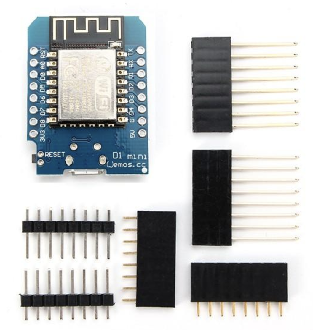
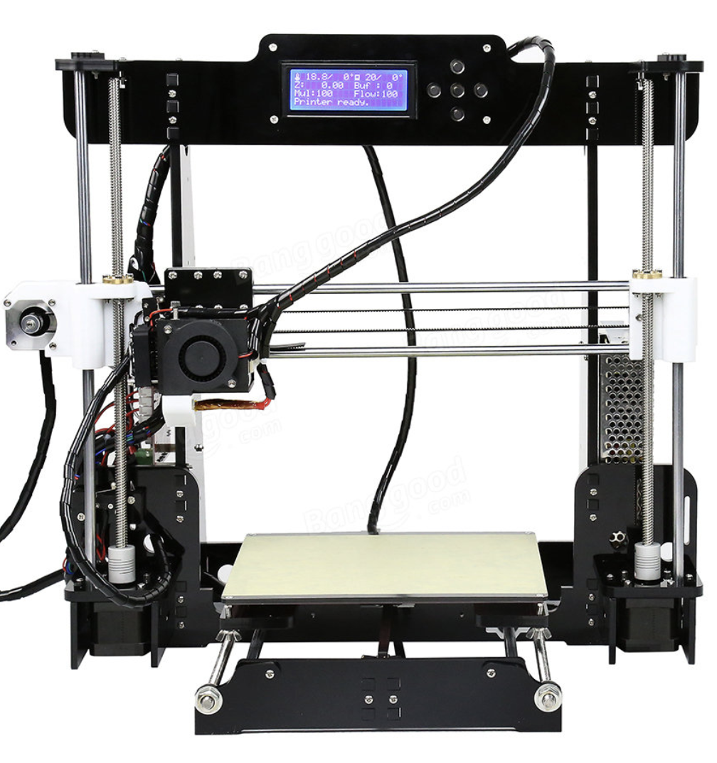
Then, around last October, I discovered the Anet A8 kit, which was being offered for import by a number of outlets, including banggood.com which is an importer that I’ve used quite a bit for getting development boards like Arduino and ESP8266/ESP32 clones.

The Anet A8 being offered from banggood

What is amazing about this 3D printer is that it is being offered as a kit at an astonishingly low price. I paid $165 for mine, shipped via DHL. I’ve seen prices hover up and down a bit, and seen kits go for as little as $140. That price point was low enough, and I read enough about people’s experience that I thought I would take a risk, and pulled the trigger.

It arrived packaged neatly in a moderately sized box. I set aside a weekend for assembly, watched a bunch of videos and set to work.

First of all, here are some of the basic features of the 3D printer.

  • It is based upon the proven open source design of the Prusa I3.
  • The frame is constructed mostly of parts which are laser cut from acrylic plastic.
  • It has a print volume of about 220x220x180 mm, which is actually pretty good.
  • It has a heated bed, and can thus print either PLA or ABS plastic.
  • It uses a custom controller board that speaks G-code, and can interface via USB as well as read gcode files directly from a microSD card.
  • It has been pretty popular, so there are lots of reviews, tips and tricks on YouTube and on the web. Replacement parts are fairly easy and inexpensive to get online.

It took me about two days and maybe a total of ten hours to assembly. The instructions are available as a PDF file on an included microSD card, and were generally pretty good, but there were several places where I was confused, and had to consult other resources or just sit and ponder to reveal how to continue. I made a couple of mistakes that I only discovered late: a mistake in assembling the X-axis meant that it operated in reverse when I first powered it on, which was confusing until I thought very carefully about what certain diagrams meant. But in the end, I encountered no real serious problems. After 10 hours, I had a pile of parts that I thought were assembled properly.

And here is where the instructions actually get a little weak. Making your first print is actually not that well described. In particular, making sure that your printer bed is level is not all that well described, and that is an essential step in getting good quality prints. The included software on the microSD card was also for Windows, and I had (and desired) no Windows box to run it on, so I knew that I would need some additional software, and that meant developing a working configuration file for the printer.

It took me about another day of on and off pondering until I thought that I had tweaked my printer enough so that I would give it a try. I took some green “glow in the dark” PLA that I had used on the Makerbot, and tried to print one of the pre processed g-code files for a Chinese chess piece from the microSD card:

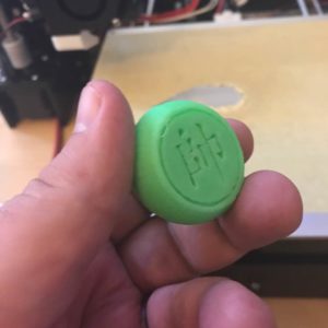
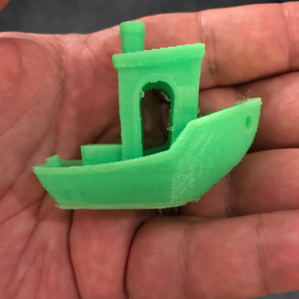
Not bad. In fact, not bad at all! I still didn’t have the bed leveling quite right. The first layer of this print was a bit uneven and high. I tweaked it, and decided to try to actually try something more challenging. The obvious to try was a Benchy which is a little toy boat which is often used as a quality benchmark. It has overhangs, smooth curves, small details, and generally is a pretty good workout for a 3D printer.

To do this, I needed to convert the STL file into a compatible G-code file. The program that came on the microSD card with the printer was an old version of Cura, and that wasn’t really going to work for me and my Linux laptop. I ended up using the open-source program slic3r, which was just an “apt-get install slic3r” command away from being installed on my Linux laptop. I used the settings for a Prusa i3, and only adjusted the bed size to match the slightly larger size of the Anet A8. I set a layer height of .2mm, the bed heat to 50 degrees C, and the filament temperature to 200 degrees C. I did not have it generate any support structures. I then clicked the “generate g code” button, saved it out, and then copied it to the microSD card, and then hoped for the best.

Here is the result:

Not bad. Not bad at all! In fact, pretty freakin’ amazing! I was ecstatic that I was getting pretty respectable results after only about three days of tinkering.

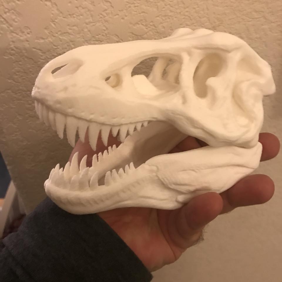
Since then, I’ve printed some more cool stuff. The most complicated thing that I’ve done to date is this dinosaur skull that I downloaded from thingiverse:

This was about 12 hours of continuous printing, using some white Solutech PLA that I bought from Fry’s Electronics. It sits on my desk at work. It’s pretty neat.

Okay, so what’s the downside?

I was happy (and mostly remain happy) but there are a few things that have been rather problematic.

First of all, in terms of general reliability, the printer has been pretty abysmal. I had a thermistor fail in the filament heater block after a few weeks of working, and it took me a white to order replacements and get them installed. Then, after just a couple of days of use, I had a thermistor sensor fail in the heated bed. I haven’t had the chance to debug this yet, but suspect that it may be something fairly simple (like the thermistor just not making contact with the heated bed and giving unreliable readings, but I have to set aside some time to dissemble the heated bed and then relevel it, so I haven’t gotten around to it yet. And this is perhaps the most annoying thing. The printer is made from parts which are sourced from the cheapest vendor imaginable, so you might imagine that you are going to have some part failures. But the overall design of the printer is such that doing some of these replacements is inconvenient or unnecessarily complicated.

For instance, the MK8 extruder is held in place by a metal bracket that slides along the X axis. It is held by a screw which is mounted somewhat inaccessibly underneath the print head (which makes it difficult to reach or even see) and a nut which is screwed onto the heat tube and clamps the stepper motor assembly. It seems like the MK8 is just designed for maximum annoyance when assembling and disassembling. I’ve had to take it apart and reassemble it multiple times, and it seems like every time I do I am looking for at least an hour of my time. It’s impossible to make any adjustment to the head without also being forced to completely re-level the bed and generally just spend a fair amount of time tweaking stuff.

The good news is that if you’ve assembled the printer, you probably have a good idea of what all the parts are and where they should go. And the parts are inexpensive. But if your goal is to have a reliable printer that you can keep running 24/7, then the Anet A8 will not be the printer for you, at least not without significant upgrades that blunt its initial low cost.

And you will be spending more money than the initial inexpensive cost will reveal. I’ve bought a bunch of heater block/thermistor replacements. I had to buy a crimping tool and a bunch of the JST connectors you use for the thermistors because none of them can be bought “pre-crimped.” The connectors are annoyingly small and difficult to crimp, and it takes me two or three tries to get them to work. I bought some additional Kapton tape. Some spiral cable guides. A set of small metric wrenches. Some additiout sonal metric hardware in stainless steel to replace cheap adjustment screws. Some white lithium grease. A roll of good quality blue masking tape to cover the bed. I suspect I’ve added easily another $100 to the cost.

A note about safety

I should also add that the design itself is not well engineered from a safety standpoint.

First of all, the entire printer is powered by a small 12V power supply which bolts to the side of the printer. To wire it up, you need to wire in a 120 volt plug (I’m in the U.S.). There is no provision for a switch or any strain relief on this cord. I got my cord from Orchard Supply and Hardware, and crimped on some spade connectors, which I then bolt in. This is what it looks like:

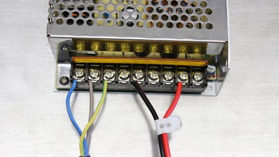
I do not consider this adequately safe. If someone trips over the cord, all sorts of bad things could happen, including a dead short across the freshly exposed connectors. If you intend to use this printer around children, then this part of the printer should be seriously upgraded to include a properly grounded case, fuses, and proper strain relief. As it is, I leave the printer unplugged when it is not in use, and unplug it, and carefully coil the power cable up. An upgrade to this part of the printer is clearly in my future.

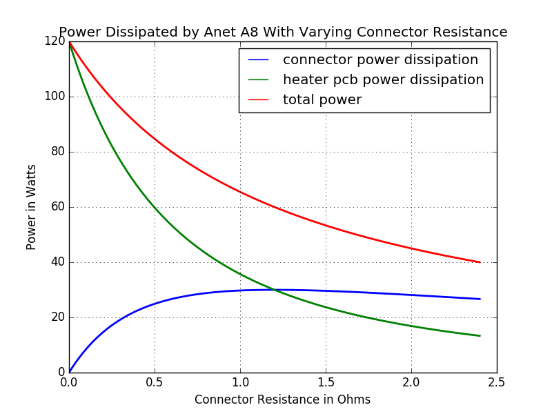
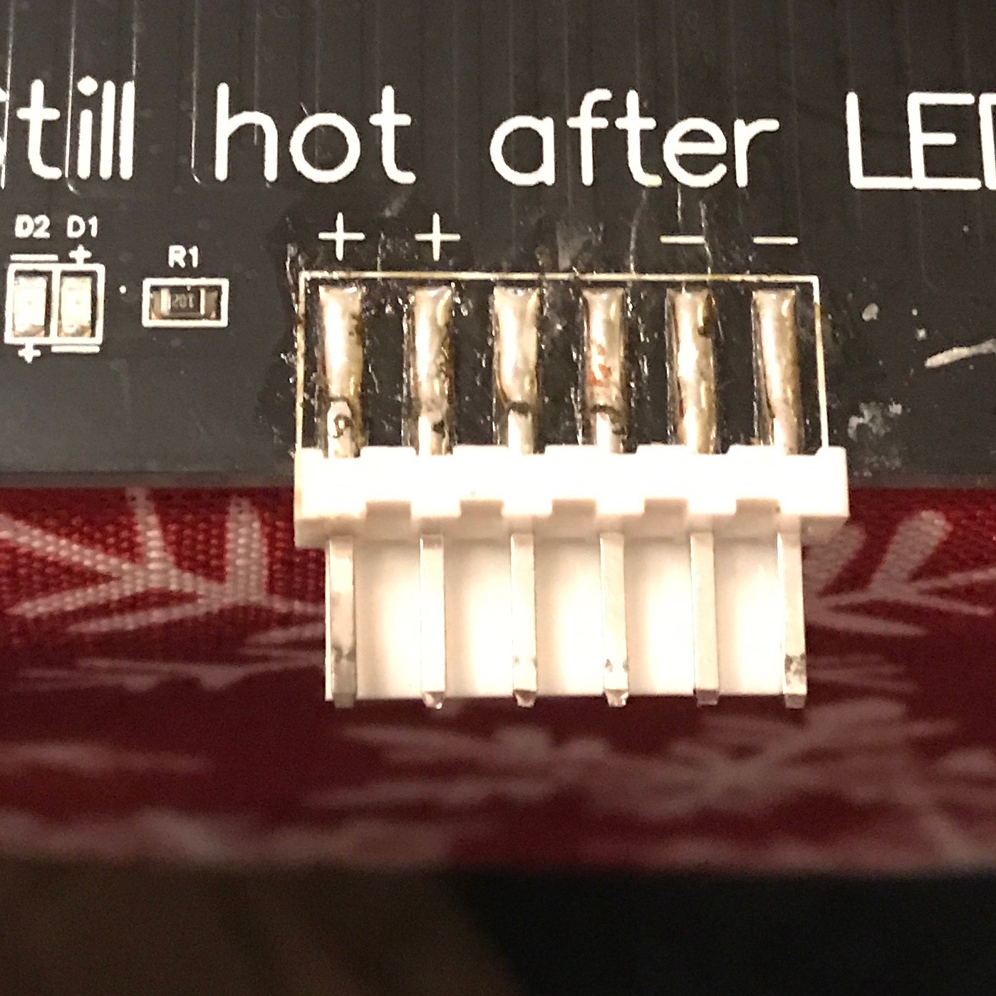
The other major safety issue is that the Anet A8 board is not engineered with appropriate connectors to handle the power necessary to drive the hot end heater block and the bed heater simultaneously. While I have had no real difficulties, there are no shortage of stories on the internet about people with melted connectors like this one:

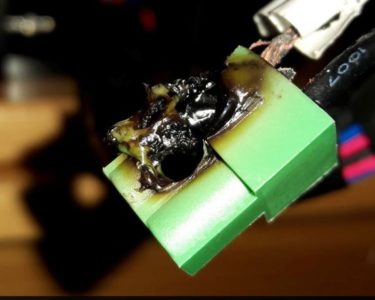
This is because the power connectors on this board are not actually properly rated for the amount of current that might be drawn through the mainboard. There are a number of ways that you can fix this shortcoming. The basic idea is to use the outputs from this board not to directly drive the bed heaters, but instead drive separate, better engineered daughter boards which use a good MOSFET and better connectors to drive the heaters. This reduces the current draw from the main board, enabling those connectors to remain cool, and shifts the power draw to the MOSFET boards which include better connectors and heatsinks. I have not yet installed those on my printers, and thus am careful not to operate the printer unattended. On long prints, I also monitor the temperature of those connectors using a non-contact infrared thermometer (yes, also bought for this product, add that to the total) and always am careful to keep a fire extinguisher handy.

In short, this is not a beginner project. If you don’t know what you are doing (or if you value your time) get a more turnkey system.

Future posts

3D printing is a big topic. I’ve also experimented with using Octopi, which is a Linux distribution for the Raspberry Pi that you can use to make printing to your Anet A8 (or any other printer) wireless (no more schlepping microSD cards around). I’ve also goofed around with PrintRun so that I can print directly from laptop. Or I could elaborate on any of the topics that I briefly introduced above. Do you have any questions, comments or suggestions? Feel free to leave them below, or leave me a note via @brainwagon on Twitter.

Mark VandeWettering

1/4/2018

I’m tired this morning, because at 2:39AM I was awoken by a magnitude 4.5 earthquake centered in Berkeley. It was over before I gained full consciousness, but it was a pretty sharp series of jolts that rattled the house pretty good. No damage.