As in most things, whether you achieve success has a lot to do with what connections you have. And this is true of my somewhat unreliable Anet A8 3D printer more than most.
My printer had been down for a month while I worked on getting a new hot end installed properly. It wasn’t so much that it was difficult, but that it simply took time to get the new parts, find an appropriate crimping tool for the thermistor, and install the new head. Mind you, reassembling the MK8 seems to be more difficult than you would think, but I am getting better at it.
I have been thinking of doing a hot end replacement to a new Bowden extruder, so I thought that while the iron was hot (so to speak) I would print the necessary brackets so I would have them on hand when I felt like that kind of tinkering. I got the stepper motor bracket printed, and was printing the necessary bracket to mount on the X-axis when I had the print fail because of a THERMAL RUNAWAY error message. A bit of debugging revealed that there was a problem not with the hot end, but with the heated bed. In particular, it seemed like it was unable to come to temperature. The controller basically jammed the current on full blast, but it seemed to stabilize at around 38 degrees Celsius instead of the desired 50 degrees.
That was where I left it a week ago.
Finally today I decided to disassemble the hot bed and see what the issue is. My suspicion was that as with the hot end, a thermistor had failed (or perhaps just become dislodged) and was no longer reading properly. I thought I’d remove the hot bed so I could examine the underside so I could see if there was any obvious problem. To remove the hot bed, you pull the four leveling bolts at the four corners, and disconnect the connector.
Looking on the underside, you can see the connector has six pins. There are two positive, two negative and two pins which go to the thermistor. You can order replacements fairly easily, for $13-$20.
But back to my broken hot bed.
Like 99% of all problems, it was pretty obvious once I looked. Here is a picture of this connector:
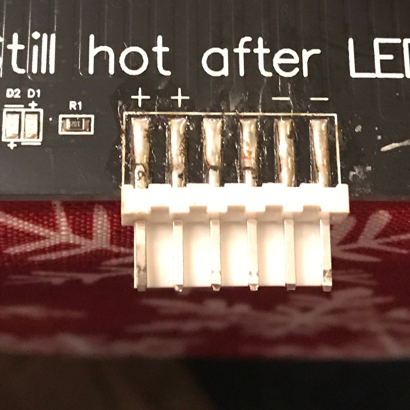
It may not be obvious in this picture, but the left most pin (wired to positive) is pretty oxidized and gray. Looking at the corresponding socket on the plug, it also appears oxidized and gray.
Normally, the resistance of the hot bed is supposed to be around 1.2 ohms. At 12V, that means that the bed should draw 10 amps and therefore about 120w. But if the connector adds just one more ohm of resistance, it basically halves the available power, and the bed may not heat very effectively. That’s what I’m thinking of doing.
Apparently these connectors do fail fairly often because they aren’t really rated for as much current as is passing through them, and they also aren’t really designed for a connection which flexes. I think what I’m going to do is remove the connector entirely and solder the wires directly to the pins. I’ll probably have to wait until this weekend.
3DPrint Wiki on replacing the Hot Bed connector
I might also take the time to do the MOSFET upgrade that people recommend for additional safety.