I’ve had a couple of DC motor control modules lying around unused for quite a while. I think that I bought them for a simple robot project back in 2013 that apparently wasn’t quite simple enough: I got distracted and never went anywhere with it. But I was watching some videos as part of my holiday binge of model railroading videos, and projects like DCC++ used the LM298 to supply power to the rails of a train.
I dug around in my box and found a couple of these modules, and thought I’d spend a little time figuring out how to use them. I’m not going to be using DCC, but am instead just going to be using ordinary DC trains, so there really isn’t any difference between a model train and any other form of DC motor. I had a pair of Pololu gear motors lying in a box, so I dusted one off and wired it up.
It’s a cute module really.
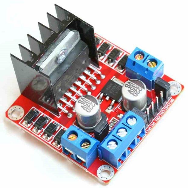
It can control two different DC motors that are connected to the pair of screw connects on the left and right of the module. On the front, you attach a power supply for the motors, with the 12V going to the leftmost of the three connections, with a ground to in the middle. If the jumper on the board is present, it will feed that to an 7805 voltage regulator, and provide it to the rightmost screw terminal as well as using it to power the module itself. You can use it to power an Arduino if you like (tie the ground and 5v to the GND and VIN for the Arduino). I didn’t bother, and instead tied the ground. In addition, I wired the leftmost ENABLE pin on the module to pin 3, and the IN1 and IN2 signals to pins 6 and 7 respectively. (I could se
Then, I set down to write some code. I didn’t have a pot or rotary encoder handy, so I thought I’d just write a simple test program that read commands and moves the motor. It’s a series of single line commands. ‘A’ or ‘B’ will switch to that motor. ‘F’ or ‘R’ will tell the motor to go forward or background. ‘0’ will disable both motors. ‘S’ followed by an integer (from 0 to 255) will set the speed of the motor.
It worked the first time I got it to compile.
// l298 test
//
// a simple program written to provide a basic serial test program
// to test a small L298 motor driver board and my understanding of it.
//

// The L298 basically uses three digital pins to drive a DC motor.
//     - an ENABLE pin, which we will drive with a PWM signal to
//       implement speed control and
//  - two INPUT pins which define the direction.
//    if both are high or both are low, then brakes are applied
//    if the first is high and the second low, then the motor is driven forward
//    if the first is low and the second high, then the motor is driven reverse

// These pins need to be PWM (analogWrite capable are 3, 5, 6, 9, 10 and 11
// on the Arduino UNO/Nano).

const int ENA = 3 ;		// enable for the A motor
const int ENB = 5 ;		// enable for the B motor

// these two pins control the direction of the A motor
const int IN1 = 6 ;
const int IN2 = 7 ;

// these two pins control the direction of the B motor
const int IN3 = 8 ;
const int IN4 = 9 ;

const char * version = "L298 TEST compiled on " __DATE__ " "  __TIME__ ;
int channel = 0 ;		// select 0 (A) or 1 (B)

void
setspeed(int s)
{
    // default arduino PWM is about 490 Hz, and uses an 8 bit value
    analogWrite(channel ? ENB : ENA, s) ;
}

void
setdirection(int d)
{
    if (d) {
	digitalWrite(channel == 0 ? IN1 : IN3, HIGH) ;
	digitalWrite(channel == 0 ? IN2 : IN4, LOW) ;
    } else {
	digitalWrite(channel == 0 ? IN1 : IN3, LOW) ;
	digitalWrite(channel == 0 ? IN2 : IN4, HIGH) ;
    }
}

void
setchannel(int c)
{
    if (c == 0 || c == 'a' || c == 'A')
	channel = 0 ;
    if (c == 1 || c == 'b' || c == 'B')
	channel = 1 ;
}

char cmd[80] ;
char *cp ;

void
processCommand()
{
    int op ;
    int val ;

    Serial.print("CMD: ") ;
    Serial.println(cmd) ;

    op = cmd[0] ;
    if (islower(op))
	op = toupper(op) ;

    switch (op) {
    case 'A':
    case 'B':
	setchannel(op) ;
	break ;
    case 'S':
        val = atoi(cmd+1) ;
	setspeed(val) ;
	break ;
    case 'F':
    case 'R':
	setdirection(op == 'F' ? 1 : 0) ;
	break ;
    case '0':
	digitalWrite(ENA, LOW) ;
        digitalWrite(ENB, LOW) ;
        break ;
    }
}

void
setup()
{
    Serial.begin(115200) ;
    Serial.println() ;
    Serial.println(version) ;

    // magic incantation to lower the PWM frequency
    // the motors that I have have an annoying resonance at the default
    // frequency (490Hz).  Lowering it to just 30Hz seems to help, and
    // also makes the motor actually function at low speed.
    // https://etechnophiles.com/change-frequency-pwm-pins-arduino-uno/
    TCCR2B = TCCR2B & B11111000 | B00000111 ;
    pinMode(ENA, OUTPUT) ;
    pinMode(IN1, OUTPUT) ;
    pinMode(IN2, OUTPUT) ;

    pinMode(ENB, OUTPUT) ;
    pinMode(IN3, OUTPUT) ;
    pinMode(IN4, OUTPUT) ;

    cp = cmd ;
}

void
loop()
{
    int c ;
    while (Serial.available()) {
	c = Serial.read() ;
	if (c == '\n') {
	     *cp = '\0' ;
	     processCommand() ;
	     cp = cmd ;
	} else {
	     *cp++ = c ;
	}
    }
}
But there was something interesting. By default, the PWM on pin 3 of the Arduino runs at around 490 Hz, and you could definitely hear it resonate when driving the motor. At very low speed, the motor actually didn’t move, but just vibrated at around 490Hz. I looked up a website that told me how to adjust the default PWM frequency. If I raised it, the motor didn’t move unless I set the value pretty high, but the whine wasn’t super audible. When I lowered the PWM frequency to around 30hz, the motor actually worked better at low speed, and you could hear the low switching tone, but it was less irritating. I hooked up a scope and observed the relatively large inductive spikes.
I’ve no real experience with motor control and things like EMF. I’ll have to do some more reading. But for now, I think it will work. Cool.
You need to discover the secret of the field coil and energy distributing PWM. The field coil is an inductor in series with the mother that tunes the impedance of the circuit, it also is the ‘current reservoir’ when your PWM signal is ‘low’ rather than high.
The second thing is that PWM is a crappy way of controlling inductive loads. You can however design 1/0 sequences of various arrangements such that the net ‘on’ time is proportional (think of it kind of like grey code for PWM).
Lastly, and perhaps obvious so forgive me if you’re already there, the voltage across the motor should be high enough such that the time constant of your PWM signal allows it to get to sufficient current to actually generate enough torque to move the motor.
And another thing, you can actually drive the motor continuously with a 50% duty cycle to the *direction* input (leave enable on all the time) which keeps the motor coils energized, then you adjust the motor direction and speed by varying the ratio of on to off time around 50/50.
Sir I am diploma student, sir I can have circuit diagram of a simple LED transmitter and LED receiver ? Please….