Over the holiday I was watching my usual raft of videos on Youtube, and got interested in the circuitry that is inside the common garden light. I have a number of super cheap $1, and if you watch any teardown videos of them, you’ll find that there is almost nothing inside them: typically a solar cell, a battery, an LED, and an inductor and usually a small 4 pin chip. I was interested in running some experiments, so I disassembled one of mine which looks like this model. I hooked up the solar cell to my multimeter, and measured about 2.5v at 12ma or so, for about 30mw of output power. The chip inside was a YX8018, and it also had a AAA NiCad battery which tells me it’s capacity is 160maH. Tiny.
These lights seldom incapable of maintaining a light (even as feeble as it is) the entire night, but I was curious about the circuits, so I went ahead and decided to try to experiment with them. My ultimate goal is to characterize the cheap solar cells, and also monitor the charge cycle of the battery. In the next few days, I’ll setup an Arduino as a data logger, and measure how the current flows in the circuit over a couple of days.
I could have used the scavenged components, but I thought it might be fun to start from scratch, and be able to make several versions of the circuit to compare and contrast. So, I ordered a pack of 20 QX5252Fs (a similar chip to the YX8018, but cheaper) for a little under $2 shipped from China. I had a couple of 100uH inductors lying around, as well as some fairly bright white LEDS. So, I breadboarded the circuit up. Instead of using the tiny AAA battery, I thought it might be good to use a reasonably high quality ENELOOP NiMH battery. Using the simple curcuit from the QX5252F datasheet and some scraps of wire, I put it up on my workbench:
It works. So, over the next few evenings I’ll begin to experiment with it some more. I wanted to experiment with changing the inductor (which modifies the LED current) and perhaps driving more than one LED to make a brighter light. I’m also interested in potentially using this setup to make a very small solar powered microcontroller project, using some additional circuitry as described here. More experimentation is clearly possible.
Readers might recall that I’ve been interested in small solar energy projects. In the past, I’ve played with a 25w solar panel, a Chinese PWM solar charge controller and a 7Ah battery, and I used it as the power source for a WSPR radio beacon that I ran for a few months in my back yard.
But last month I got more interested in using very tiny solar cells to harvest power and power very small applications, like powering garden lights or maybe running very small microcontrollers in low energy applications. So, I ordered 10 small 5v, 60ma solar cells from Banggood for about $1 each.
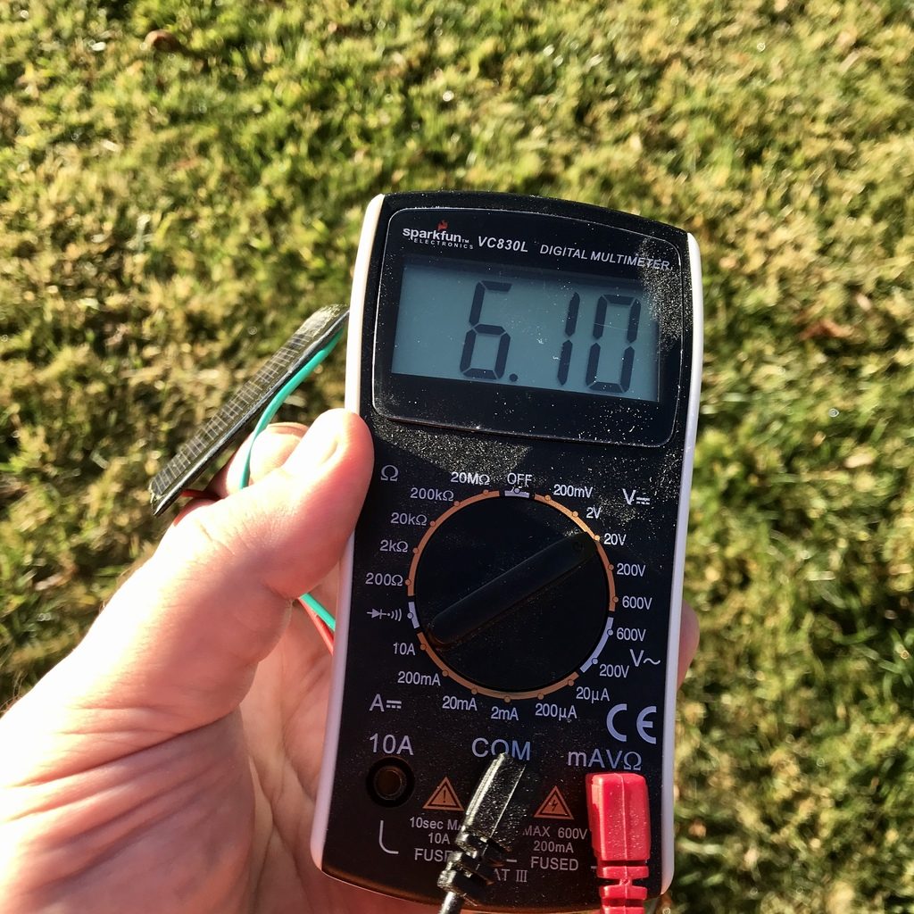
They arrived yesterday. I was feeling kind of bored this morning, so I soldered some clips on one of them, and then went outside with my snazzy Sparkfun multimeter that I got as swag from the Hackaday Superconference and tried aiming it at the sun to see what I got. Mind you, it was only 9:00AM, and we are still in January so the sun isn’t particularly bright, although it was clear.
And the results were pretty good for voltage:
6.1 volts…
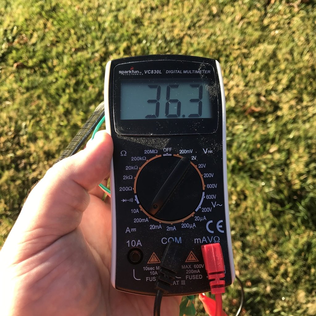
But less so for current. I only got about 36 milliamps instead of the specified 60ma. But again, middle of winter, early morning, not too bad.
36 milliamps…
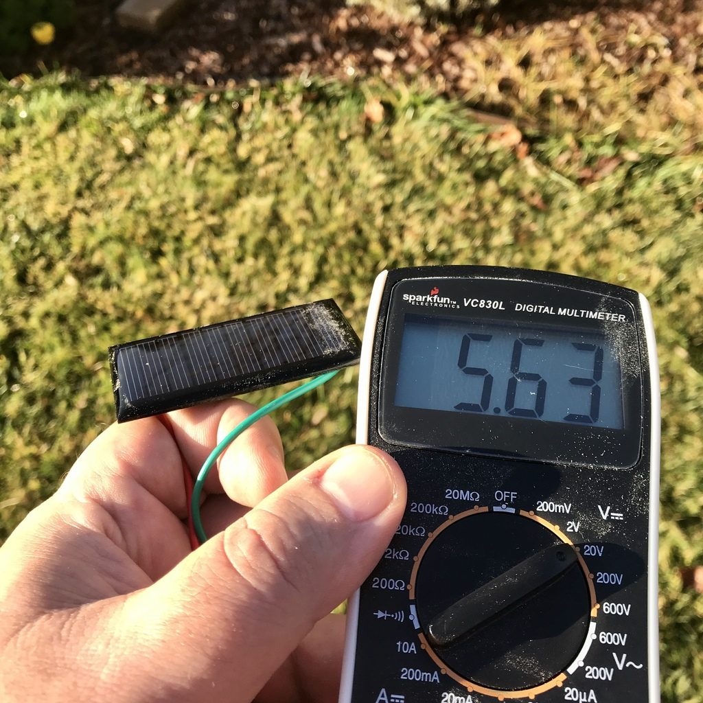
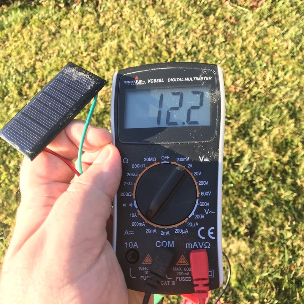
I also decided to see what kind of voltage and current I could get if I oriented the cell unoptimally, roughly straight up.
Voltage drops to about 5.63 volts…And just around 12ma.
The result was about 5.63v at just 12ma, which is perhaps better than I might have expected.
All in all, I’m fairly pleased (although I haven’t tested them all). I suspect I could have gotten similar performance by looting $1 garden lights from Dollar Tree, but I think they will still be useful and will find their way into an experiment later on. I also ordered some QX5252F chips from ebay which should arrive “any day now”. These are popular in homebrew (and commercial) solar garden light circuits. It will be fun to play with them.
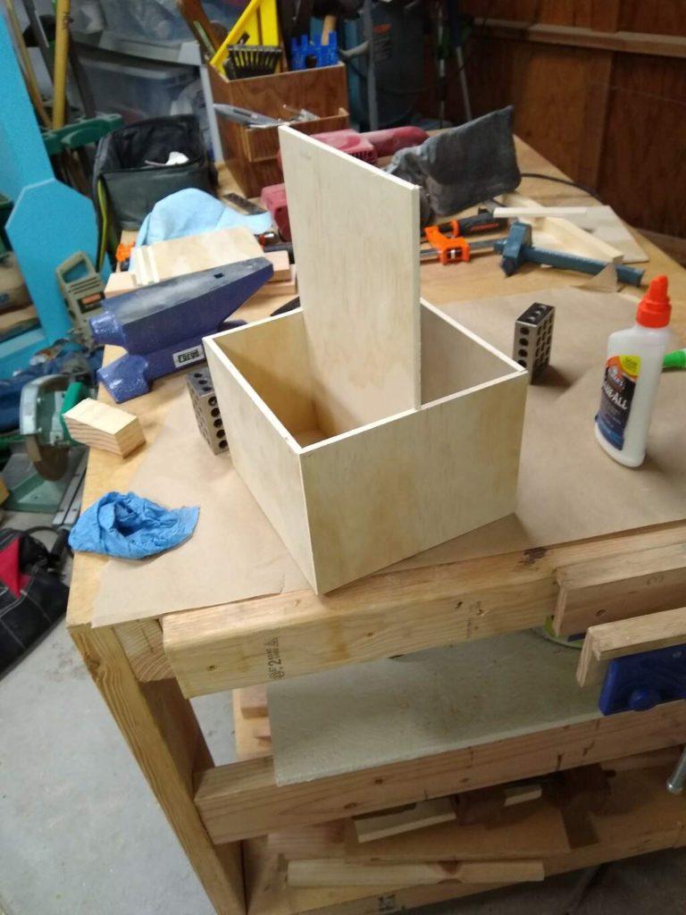
In my garage, I’m trying to do some simple skill building exercises to increase my precision and knowledge about how to construct useful objects. The recent kerfmaker and half lap projects that I’ve tweeted about were part of this attempt. Last night, after a full day of chasing pixel problems, I thought it would be fun to go into the workshop and use my kerfmaker to try to make a simple tool tote out of some scrap 1/4″ plywood that I had lying around.
I had gotten a tool tote for $1 or so at some garage sale, and had found it so useful that I had constructed a very similar tote myself a month later. But that tote was all butt joints and had the bottom merely cut to size and glued to the bottom, and I used brad nails to hold it together along with glue. I thought that maybe I make a similar (but slightly smaller) tote. I spent an hour and a half, and put together this:
Each of the sides is 8″ side. The front and back are rabetted and have a central dado to take center divider, and a dado to hold the bottom in a recess. The two sides just have the bottom dado. I dried assembled, and things looked “okay” (more on that later) so I glued the side joints, and assembled the four sides and bottom (the bottom just rested in the dado without any glue) and let it dry. I’m going to taper the middle and cut a slot in the center divider to serve as a handle. My experience with the similar tote I made before is that the properly glued joints will be plenty strong to handle whatever load I’m likely to put in it.
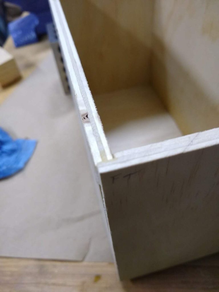
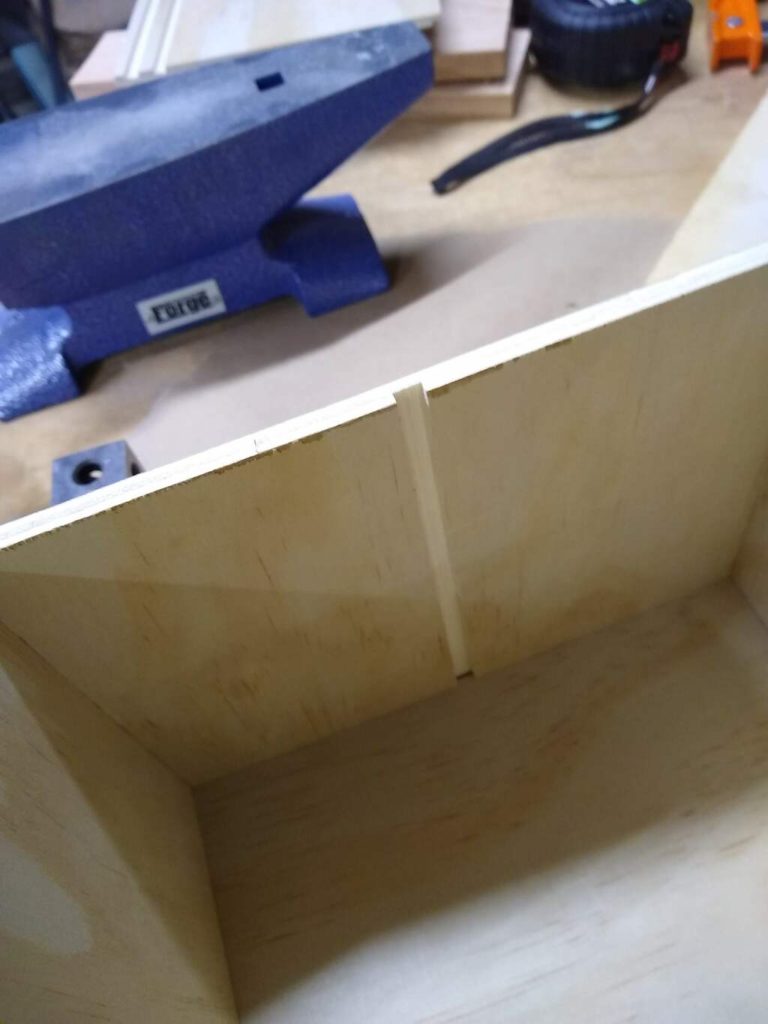
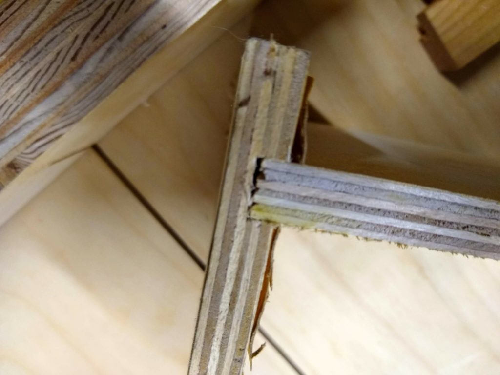
It looks pretty good, but there are a few niggly details, most notably that it doesn’t rest entirely flat on the desk. That is because the corners look like this:
The front panel here slightly protrudes. I believe this is because the dado I cut to receive the shot isn’t 100% parallel to the bottom, and so when I clamped the bottom in place, it pulled these sides out of flush/square by about 1/2 mm. Oh well, that’s what my sander is for.
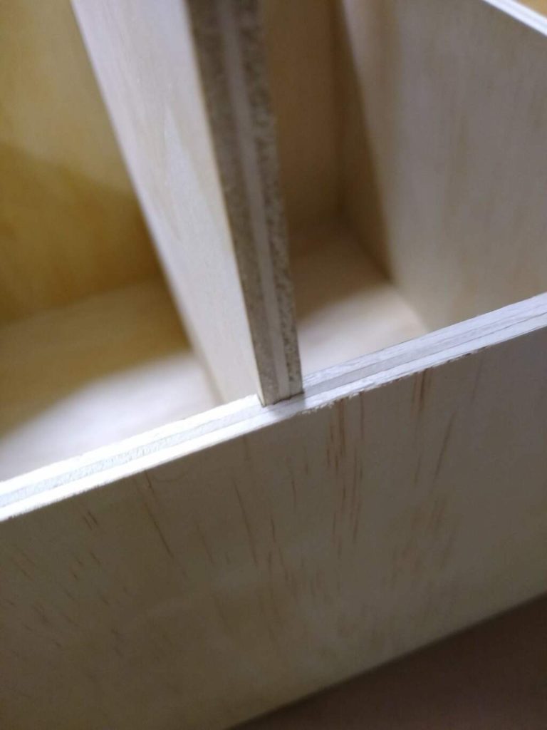
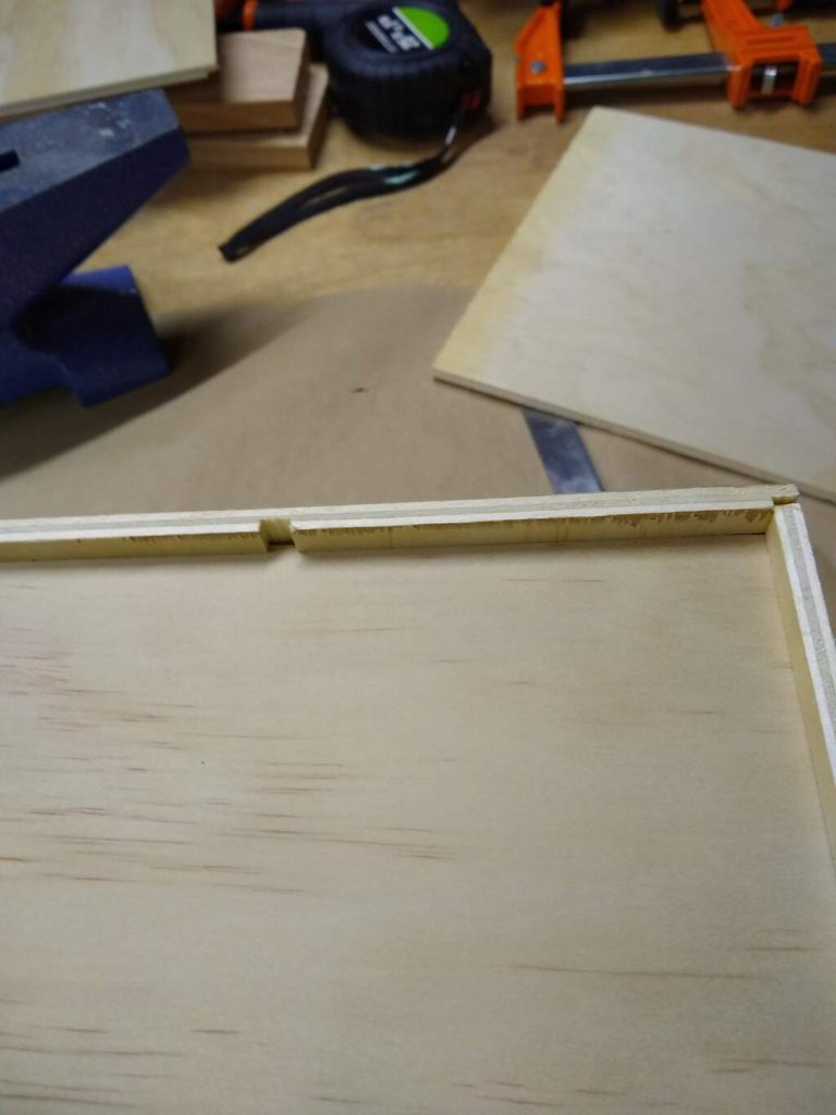
Some other pictures below. If the mood suits me, I’ll finish the tote in another evening or so.
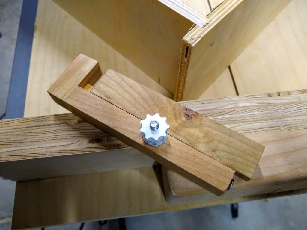
Closeup of the center divider fit into the side.Minor nit, the dado in the sides protrudes through the bottom. (Shrug). The bottom is nicely offset and dadoed into all four sides, and isn’t glued.The center dividing dado. Looks pretty clean. Could be just the tiniest fraction tighter, but slides in well.
On one of the Facebook model train groups I was in, I read an article about someone who was building a transistorized throttle based upon a design called the “Pacematic”. I did a bit of googling, and found this description. It seems like a relatively simple circuit based upon the 555 timer. I started digging around and also found this page which lists a lot of transistorized circuits for driving model trains:
I find this kind of stuff fairly interesting. Still, I think these circuits are mostly of historical interest. Now, with the availability of cheap microcontrollers and DC motor drivers, it seems like you can make far more versatile and powerful throttle control circuits. As soon as my new N scale network gets up and running, I’ll have an update of what I’m doing.
I am still an absolute rookie woodworker, which means that time spent in the shop doing the most basic skill building exercises can be fun. My previously mentioned “skill building” exercise of making a pair of simple boxes had met with the approval of our supurrvisor.
Js there catnip in here?
I cut all the rabbets for these on the table saw using my (pretty crude) cross cut sled. I had used it before to make a simple set of small display shelves, but had mostly laid out and cut dadoes by hand, with the net result that some were tight and some were loose. All in all, it made things a little fussier than I would like. That’s when I learned about a gadget known as a kerfmaker: a little adjustable spacer block that you can use to cut perfect dadoes using your table saw without any tedious and error prone measuring. Rather than explain the theory, I’ll point you at the video that I used as the basis of mine, which shows how to make one and served as the inspiration for mine.
From the excellent “Pask Makes” channel, you should subscribe.
Without further ado, here is the one I made.
A couple of notes. I still have mostly soft wood 2x4s as scrap around, as I haven’t had the confidence to ruin nice hardwood with my experiments. So I went out and spent a few bucks to get a small piece of cherry from Home Depot. This piece was cut from a piece which was 0.75″ x 1.5″. The first thing I did was cut it to rough length and then cut the rabbets in each side on the table saw. I screwed up my first one, so ended up ripping the overall size down to just 1″ wide, and I still managed to slightly botch the rabbet, but it was serviceable. This made the overall width of the jig rather narrow, which means that if I use it with some stop blocks, they have to be fairly narrow themselves. I’ll probably make a second one and do a better job.
Ideally when you rabbet this piece it will be perfectly split the piece in half, but if you want an error, you probably want to leave the tongue side slightly wide so the washer will grip the sliding part tightly.
I used 1/4″ hardware on mine because I use 1/4″ hardware all the time and that’s what I have lying around. I also printed some knobs on my 3d printer that house a nut. This had an advantage that the nut is a bit smaller than your typical 1/4×20 wing nut. Were I to do it again, I might strongly consider using smaller hardware (say, a #8 machine bolt), but I think the 3d printed nuts are really nice.
I also should note that I screwed up the set screw on the end. I had some 1″ #8 woodscrews. You want to make a pilot hole in the end. Rather than just selecting a small screw by eye, I looked up what the size should be on a table on the Internet, and it suggested 11/64″ for hardwood. I selected that drill, drilled the hole, and went to add the #8 screw and it was WAY too big. It appears that I read the table wrong (the column was for “tapered drills” which seems really annoying). As it happens a #10 wood screw would work okay (it bites in, but turns a little easy), so I just did that instead. When I build my next one, I’ll use #8 and do a better job.
I found a scrap of really crappy plywood and tried to do my first test. It was a bit loose, so I loosened the offset screw a little bit and tried again. The second attempt resulted in a nice dado that wasn’t hard to assemble, but was tight enough that friction would hold it in place. Huzzah!
One last thing: the overall size of my kerfmaker is six inches, and is sized so it would reasonable work to cut half lap joints in 2x4s. I think if we made a smaller one it would be pretty useful. I also think that it might be a good time to make a better (and wider) version of my cross cut sled, perhaps with a T-track along the top to clamp and hold stop blocks.
A friend of mine pointed out an interesting website today: applesearch.org. This is well and truly off my normal set of blog topics (as ill defined as those might seem) but I must admit that I find it fascinating.
See, apples are fascinating.
Most people can name five or six varieties of apples, and if you dig you might be able to come up with a dozen or so. But there are over 7,500 known cultivars (CULTIvated VARietys) of apples. Apples have been cultivated for a long time and used for a wide variety of purposes: for storage, for fresh eating, for cooking, for making cider, and even for livestock.
But this huge diversity of cultivated varieties are being totally dominated by just a few varieties which are selected mostly for looks and their ability to get to market in a cosmetically appealing state. No greater example need be presented than the misnamed “Red Delicious” apple, which is actually red, but to my taste is cruelly misnamed. I am not alone in this opinion. They are generally mealy and not at all to my liking, and its popularity has been falling since the introduction of other commercial varieties.
The story of the Red Delicious is an interesting story in itself.
But there is also an interesting genetic mechanism at work that has allowed so many different cultivars to be developed.
The odd thing about apples is that if you grow an apple tree from seed, chances are excellent that the fruit produced will be almost completely unlike the fruit of its “parent” tree. Apples possess a property called ‘extreme heterozygosity’. The entire industrial production of apples relies on grafting: taking stock from a particular tree that you like, and literally adding that branch to a new sapling where it can develop into a clone of the existing stock. This can even lead to “multi-grafted” apple trees, where several different varieties are grown on a single tree.
Anyway, I think that apples are cool.
Back to applesearch.
It’s the work of a gentleman named Tom Brown, who sees the dwindling of variety in apple cultivars to be something that he’s willing to dedicate his time and enthusiasm to combat. He basically goes around doing research and trying to identify varieties of apples which were thought to be lost, and find living stock. He does this largely by talking to old people about apples. He then cultivates them and makes them available to others who many wish to keep the varieties alive.
I think that’s a pretty darned cool way to spend your life.
Addendum: I rather like Pink Lady apples for applesauce.
The recipe couldn’t be simpler. A pound and a half of apples. Cut and cube up. If you have a food mill, then don’t even bother peeling. Add 1/2 cup of water, 3 tablespoons of sugar and a tiny amount (1/4 teaspoon) of cinnamon, and a dash of cardamom if you have it. Cook for 20 minutes over medium heat until the apples are soft. If you have the food mill, run it through that and all the peel will be left (although it will lend a rosy pink color to the sauce). If you peeled them, you can just have at it with a potato masher.
Home made applesauce (particularly the fresh sort like this) is delicious.
I’ve had a couple of DC motor control modules lying around unused for quite a while. I think that I bought them for a simple robot project back in 2013 that apparently wasn’t quite simple enough: I got distracted and never went anywhere with it. But I was watching some videos as part of my holiday binge of model railroading videos, and projects like DCC++ used the LM298 to supply power to the rails of a train.
I dug around in my box and found a couple of these modules, and thought I’d spend a little time figuring out how to use them. I’m not going to be using DCC, but am instead just going to be using ordinary DC trains, so there really isn’t any difference between a model train and any other form of DC motor. I had a pair of Pololu gear motors lying in a box, so I dusted one off and wired it up.
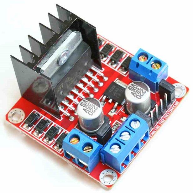
It’s a cute module really.
It can control two different DC motors that are connected to the pair of screw connects on the left and right of the module. On the front, you attach a power supply for the motors, with the 12V going to the leftmost of the three connections, with a ground to in the middle. If the jumper on the board is present, it will feed that to an 7805 voltage regulator, and provide it to the rightmost screw terminal as well as using it to power the module itself. You can use it to power an Arduino if you like (tie the ground and 5v to the GND and VIN for the Arduino). I didn’t bother, and instead tied the ground. In addition, I wired the leftmost ENABLE pin on the module to pin 3, and the IN1 and IN2 signals to pins 6 and 7 respectively. (I could se
Then, I set down to write some code. I didn’t have a pot or rotary encoder handy, so I thought I’d just write a simple test program that read commands and moves the motor. It’s a series of single line commands. ‘A’ or ‘B’ will switch to that motor. ‘F’ or ‘R’ will tell the motor to go forward or background. ‘0’ will disable both motors. ‘S’ followed by an integer (from 0 to 255) will set the speed of the motor.
It worked the first time I got it to compile.
// l298 test
//
// a simple program written to provide a basic serial test program
// to test a small L298 motor driver board and my understanding of it.
//

// The L298 basically uses three digital pins to drive a DC motor.
//     - an ENABLE pin, which we will drive with a PWM signal to
//       implement speed control and
//  - two INPUT pins which define the direction.
//    if both are high or both are low, then brakes are applied
//    if the first is high and the second low, then the motor is driven forward
//    if the first is low and the second high, then the motor is driven reverse

// These pins need to be PWM (analogWrite capable are 3, 5, 6, 9, 10 and 11
// on the Arduino UNO/Nano).

const int ENA = 3 ;		// enable for the A motor
const int ENB = 5 ;		// enable for the B motor

// these two pins control the direction of the A motor
const int IN1 = 6 ;
const int IN2 = 7 ;

// these two pins control the direction of the B motor
const int IN3 = 8 ;
const int IN4 = 9 ;

const char * version = "L298 TEST compiled on " __DATE__ " "  __TIME__ ;
int channel = 0 ;		// select 0 (A) or 1 (B)

void
setspeed(int s)
{
    // default arduino PWM is about 490 Hz, and uses an 8 bit value
    analogWrite(channel ? ENB : ENA, s) ;
}

void
setdirection(int d)
{
    if (d) {
	digitalWrite(channel == 0 ? IN1 : IN3, HIGH) ;
	digitalWrite(channel == 0 ? IN2 : IN4, LOW) ;
    } else {
	digitalWrite(channel == 0 ? IN1 : IN3, LOW) ;
	digitalWrite(channel == 0 ? IN2 : IN4, HIGH) ;
    }
}

void
setchannel(int c)
{
    if (c == 0 || c == 'a' || c == 'A')
	channel = 0 ;
    if (c == 1 || c == 'b' || c == 'B')
	channel = 1 ;
}

char cmd[80] ;
char *cp ;

void
processCommand()
{
    int op ;
    int val ;

    Serial.print("CMD: ") ;
    Serial.println(cmd) ;

    op = cmd[0] ;
    if (islower(op))
	op = toupper(op) ;

    switch (op) {
    case 'A':
    case 'B':
	setchannel(op) ;
	break ;
    case 'S':
        val = atoi(cmd+1) ;
	setspeed(val) ;
	break ;
    case 'F':
    case 'R':
	setdirection(op == 'F' ? 1 : 0) ;
	break ;
    case '0':
	digitalWrite(ENA, LOW) ;
        digitalWrite(ENB, LOW) ;
        break ;
    }
}

void
setup()
{
    Serial.begin(115200) ;
    Serial.println() ;
    Serial.println(version) ;

    // magic incantation to lower the PWM frequency
    // the motors that I have have an annoying resonance at the default
    // frequency (490Hz).  Lowering it to just 30Hz seems to help, and
    // also makes the motor actually function at low speed.
    // https://etechnophiles.com/change-frequency-pwm-pins-arduino-uno/
    TCCR2B = TCCR2B & B11111000 | B00000111 ;
    pinMode(ENA, OUTPUT) ;
    pinMode(IN1, OUTPUT) ;
    pinMode(IN2, OUTPUT) ;

    pinMode(ENB, OUTPUT) ;
    pinMode(IN3, OUTPUT) ;
    pinMode(IN4, OUTPUT) ;

    cp = cmd ;
}

void
loop()
{
    int c ;
    while (Serial.available()) {
	c = Serial.read() ;
	if (c == '\n') {
	     *cp = '\0' ;
	     processCommand() ;
	     cp = cmd ;
	} else {
	     *cp++ = c ;
	}
    }
}
But there was something interesting. By default, the PWM on pin 3 of the Arduino runs at around 490 Hz, and you could definitely hear it resonate when driving the motor. At very low speed, the motor actually didn’t move, but just vibrated at around 490Hz. I looked up a website that told me how to adjust the default PWM frequency. If I raised it, the motor didn’t move unless I set the value pretty high, but the whine wasn’t super audible. When I lowered the PWM frequency to around 30hz, the motor actually worked better at low speed, and you could hear the low switching tone, but it was less irritating. I hooked up a scope and observed the relatively large inductive spikes.
I’ve no real experience with motor control and things like EMF. I’ll have to do some more reading. But for now, I think it will work. Cool.
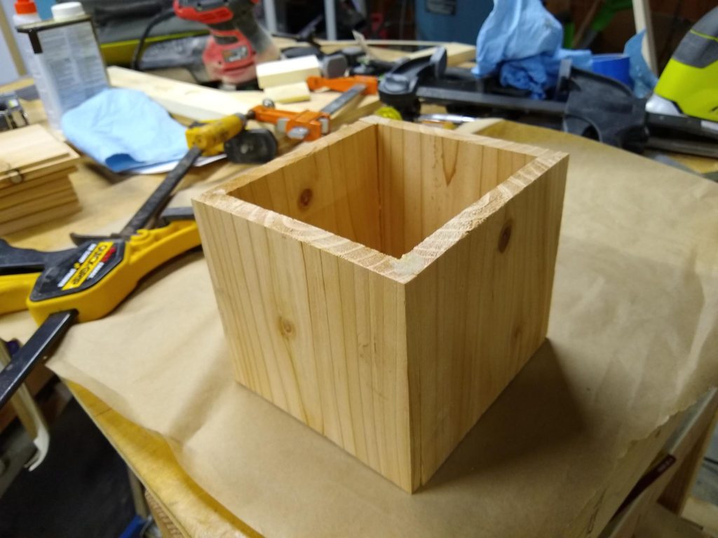
Carmen thought I should spend a little more time in the shop today. I didn’t have anything in mind, but while poking around we found a chunk of cedar fencing that I had used as a test for my jointer. We had jointed it down to around 0.47″ thick, although it wasn’t particularly uniform: I hadn’t gotten my thickness planer back then, so it’s quite possible it had a fair taper in thickness, and it was by no means flat.
But it was cheap, and lying around, so I thought that it might be fun to practice making some simple boxes. The idea was to simply cut some lengths of the board to 5″, and cut rabbets 1/4″ wide and 1/4″ deep on three sides of each of the four pieces that will form the side and on all four sides of a fifth piece that will serve as the bottom. I used my (not very accurate) cross cut sled and set it with a stop block so it would cut a slot half the thickness of the board, and then adjusted the table saw so it would cut half the thickness high. I don’t have any gauge blocks, so I just used a drill bit and adjusted it so the teeth were flush with a 1/4″ drill bit. I then just “nibbled” the rabbet out with multiple passes.
It took me about fifteen minutes to cut all the rabbets on the ten pieces. I then squirted some Titebond II into the joints, and clamped it all together. The fit wasn’t amazing, but was credible and a little sanding (especially on this super soft cedar) will probably tidy it up to reasonable levels. I’ll get a picture tomorrow when its done.
Every time I do one of these projects, I try to think about how I could have done it better. I think a few sources of error are likely:
The lumber was cheap, soft and really warped. You can’t expect micron precision from a board which has over a half inch of bow in its six foot length.
The lumber was not sized properly. If I really cared, I’d probably joint one edge and one face, then rip the stock to a consistent with and run the stock through my thickness planer.
The most obvious problem is that my cross-cut sled isn’t particularly square (I suspect about 1/4 degree or so, which actually adds up to around half a millimeter over a five inch span). I should try to make something better in the future.
I also am using a conventional sawblade which leaves a somewhat jagged profile, it would likely be better to use a flat bottom blade.
But in any case, a few passes with my random orbit sander will turn the box into something that I could finish with some Danish oil or poly and used to display dried flowers or hold keys or … well.. it’s a box.
Still, a very simple box, and a nice little shop project to close out 2019.
Happy New Year’s Eve, all.
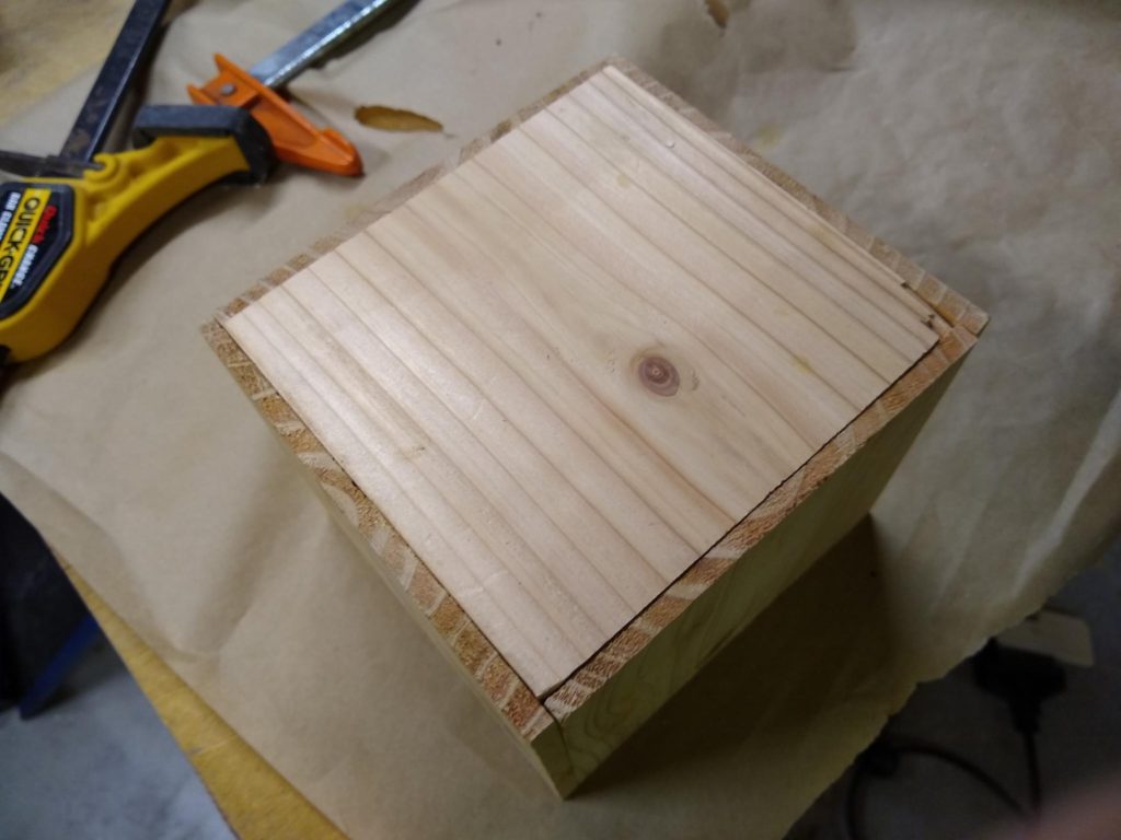
Addendum: here is the box out of the clamps. It’s not amazing or anything, and because of the warping and general unevenness of the material, the joints aren’t as even or as tight as I like. But as I said before, a couple of coats of wipe on finish and it will be a useful little container for flowers or keys or whatever. It’s also pretty good practice for making drawers.
“It’s a box. Only a bit more sophisticated than a block of wood.”The bottom had some tear out, and is about 1/2 a mm off, but with some sanding will likely be just fine.
This isn’t the most amazing way to make a box. The more “proper” but still easy way would be to use a technique like this, but I don’t have a dado stack for my saw, and it would (I think) require a change in the setup to cut with a narrower blade. Still, I might give it a whirl anyway. My next bit of shop furniture will almost certainly include drawers, so I need the practice.
Addendum to the Addendum: No doubt some will complain that the way I did this was wrong: that you need a dado to hold the rabbeted bottom into the drawer, and that only using glue is a recipe for disaster. I’ll defer to more talented and experienced woodworkers than I to answer this criticism (although I must admit that I think his generalization of his small scale tests to larger scale tests is completely off base, and there is every reason to believe that the strength of a drawer bottom that is glued in place drops as the size goes up, not increases as he suggests). But in any case, the wood here is very soft and frankly weak, and this isn’t meant to hold a great deal of weight or take a beating. And, it was just a practice. When you build stuff in your workshop, you can build it to your expectations.
Yesterday I did some work in the shop, finishing up a couple of small projects and prototyping a small display shelf for Carmen. The result was a fair amount of sawdust everywhere, so today I spent some time today vacuuming and tidying, putting away tools and generally just enjoying being in the shop. It just felt virtuous.
But I’m actually pretty bad at organization, so it took a while.
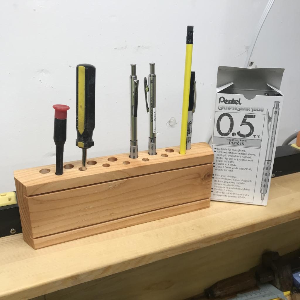
One of the things that I have trouble keeping track of is just pens and pencils. Carmen had actually bought me an actual box of Pentel GraphGear 1000 pencils (actually, the PG1015, with the 0.5″ lead, which are truly awesome incidently, highly recommended) for me to keep in the workshop, but it is shocking the number of times I put down a pencil and then seemingly can’t find it again.
While cleaning, I decided that I should make a single place where I can put my pencils, in the hope that I will actually keep track of them. So I picked up a chunk of 2×4 that was lying on the ground and instead of continuing to clean, I made more of a mess, albeit in the interest of organization.
It’s really nothing but a block of wood with some holes bored in it.
Okay, I did a bit more. There are two offset rows of holes of different sizes. The back holes are 7/16″ which is good enough to hold my new mechanical pencils as well as Sharpies. The front row of holes are 5/16″ in size, which is good for regular pencils, as well as a couple of small handy screw drivers. I did a little bit of shaping. Each end has a 22.5 degree bevel and the top is sloped by 5 degrees. I also cut a couple of shallow grooves on my table saw just to make it look nicer. I sanded it down with some 120 and then 220 sandpaper, and then rubbed on a coat of Danish Oil. It took about twenty minutes to make, most of which was boring holes.
Hopefullly I’ll now have a place to return my pencils to, so the investment that Carmen made in nifty mechanical pencils will not be wasted. This is actually just a prototype: I want to build a more elaborate caddy that includes some other spaces for basic tools like a small ruler, a small square, a couple pairs of pliers, my complete set of small screwdrivers, and maybe even some Allen wrenches. But we’ll see how much this helps first.
I’ve got a week off before crunch time really begins at work, so I’m home enjoying the company of the missus and just relaxing. And, for some reason, I’m thinking about model trains.
Mind you, I’ve always been pretty interested in model trains (and model making in general) although it never really rose to be a real hobby of mine. But something tickled my brain recently about it, and I’ve been doing some reading and watching of YouTube videos, and thought I’d write down some thoughts here.
I think that part of what got me thinking about this was realizing that unlike the old DC/rheostat control that was typical when I was a kid is no longer the only game in town. Traditional DC control had no intelligence whatsoever in the train. The tracks basically form a DC power supply for trains. Higher voltage on the rails makes the train go faster. But this means that you can’t really run two trains at the same time: they would both get the same voltage and would have to move in tandem. But even that doesn’t really work out, as the two locomotives likely respond to voltage differently and one would rapidly catch up to the the other.
Thus, if you are going to make large layouts, you end up dividing your track into zones, with complicated switching and separate power supplies and throttles to help you move trains between zones without creating a short circuit. Indeed, making such complex networks is part of the attraction for some in the model train hobby.
But advances in electronic control mean that it’s possible to do things a different way, by embedding some intelligence in the trains, and using the track not just as a simple power supply, but as an actual communication and power bus that can send control signals to individually addressed locomotives. The most popular of these seems to be DCC, or Digital Command Control.
The basic idea of DCC is that instead of using the rails as a simple power wire, the wires now encode a digital signal which can be used to transmit data packets to locomotives or other accessories like switches. Let’s call the two rails A and B. In a normal DC train, the difference between the two voltages on A and B would be considered the control signal. More voltage makes the train go faster. Reversing the polarity makes the train reverse direction. But in DCC, rail A and rail B are always of opposite polarity. The trains work by rectifying this essentially AC signal to provide a DC power voltage that they can then adjust (via a buck converter, essentially) to power the motor. But in addition to providing power, the signals convey digital information to the locomotive by flipping polarity. If the polarity switches in around 58us, then a 1 bit is being sent, where if the polarity shifts on something more like 100us, then it’s a 0 bit. The DCC specification tells you how you can form data packets. Decoders built into locomotives or track accessories have addresses, and so you can send data to individual items on your network. This means that you can have two locomotives (or more) sharing the same section of track, but getting independent control signals to tell them to move independently.
Neat.
But frankly, kind of expensive. Instead of just a transformer with a knob, commercially produced “command controllers” are significantly expensive, running well over $100 and up to several hundred dollars. That seems pretty steep.
But then I started reading about some clever guys who decided to use Arduino controllers to build their own command stations. The basic realization is that an Arduino combined with a Motor Shield (which is really just an H-bridge) can (with the addition of proper software) generate the necessary signals onto the track to control DCC ready locomotives. And luckily, someone has already gone to the trouble of writing the software. The basic details are described pretty well here:
It should be noted that in reality you can probably build the system for about $10 by ordering parts from China.
But I don’t have a fancy DCC equipped locomotive, and don’t think that spending money to get one is the best way to start working in a hobby I’m not sure is going to stick. But I got to thinking about it, and realized that I could use the same hardware to make a simple DC controller too. I’m not the first to think of that, in fact, the same guy who made the video above suggested it:
In a binge of thinking about this, I signed up for a couple of Facebook groups on budget model railroading, and someone asked the question “why aren’t people using wireless/bluetooth for this kind of stuff?” And that is actually a very good question. It coalesced with some thinking that I had been doing, which basically fall into the “why aren’t people homebrewing more control electronics for model trains?” After all, services like JLCPCB enable you to make professional circuit boards for very cheap. Arduino Nanos cost about $3 each, and a similar cost for LM398 H bridge modules. And sensors of all types are actually easy to get.
Projects like DCC++ are great because they allow interoperability with commercial modules and locomotives, but what if you didn’t actually care about that? One thing that I thought was pretty antiquated was that while it is pretty straightforward to send signals to locomotives, DCC doesn’t do a lot to help you get signals back from sensors around the layout.
I began to wonder if someone else had gone down this path. And a gentleman by the name of Steve Massiker has. He has the website arduinorailwaycontrol.com which is pretty nifty. He has a board he calls the URB (Universal Railway Board) which is basically just a motherboard for an Arduino Nano and a Darlington driver chip (the ULN2003, which is common and cheap), and communicates with other such boards via the I2C bus and with your phone via Bluetooth. Very neat. What’s super cool is that he also has the Gerber files available for free download, so you can have them made up with your favorite PCB board manufacturer. I was sufficiently intrigued that I ordered 5 from JLCPCB for $18 with DHL shipping. I should get them next week.
All this pondering may result in nothing. In particular, my job is taking up a lot of my time, and I think about far more projects than I actually start, and start far more than I finish. But I am going to keep this in the back of my head.
Any of my readers actual model railroad enthusiasts? Feel free to get to me via twitter or leave a comment below.
Brace yourself for old guy reminiscing about the past.
Back in 1980, I was a sixteen year old kid with a goal: to buy my own computer. I spent a year mowing lawns and doing chores, mostly for my grandmother, and slowly began to tease together money. By the end of the year, I had saved up somewhere north of $300, and my mom had agreed to fork over the rest of the money to purchase an Atari 400, which if memory served was around $429.
This was the catalyst for a lot which came after. My interest in computers, my major in college, my love affair with computer graphics and ultimately my career all started with the ability to program a computer that didn’t even have a storage device (I’d eventually get a cassette drive, and later an Atari 810 disk drive). The Atari was the start of it, and I bless my mom and my grandmother for giving a sixteen year old the chance to get started in something that frankly seemed like a pointless extravagance.
My life could have gone a significantly different way.
Lately I’ve been interested in restoring old tools, largely as part of getting my shop up and running. It just feels virtuous somehow to take old tools and get them able to be used again.
And so, my current spare time project: to get my Atari 400 up and running again.
Yes, I still have it, along with an Atari 130XE that I believe was my brother’s, and the Atari 810 drive and an Atari 1200 baud modem. They passed around and somehow I never chose to get rid of them. But they hadn’t been turned on in something like 20 years.
Until a few weeks ago, when I decided to try it. I recorded a bunch of short videos on my iPhone and made a playlist of them. They weren’t scripted, rehearsed, or even edited, but I made this playlist of them.
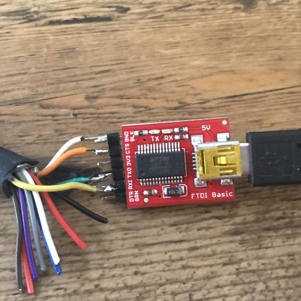
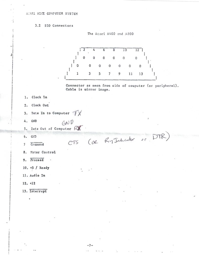
The culmination of this was to actually boot the Atari from a floppy. But again, as I said I do have a floppy drive (in as yet undetermined condition) but I read that there was a way to make a serial cable that could make your laptop serve as a floppy disk drive. As it turns out, it’s really easy. While the Atari SIO connector has thirteen pins, it turns out that you really only need four of them to be connected, and that can be done by with a standard FTDI USB to serial converter.
I didn’t film my assembly of one, since it turned out to be so simple. I cut apart my spare (somewhat bedraggled) SIO cable, and then just stripped and soldered the wires to a small row of male header pins so that they could be connected to the Sparkfun 5V FTDI USB/Serial adapter. Here is a closeup that pretty much tells you the entire story:
This is all there is to the cable…
I’ve no idea whether the colors inside Atari SIO cables are standard, so you might want to double check using my notes below. On my cable, ground was actually a white wire with a black stripe (hard to see above) and there is a seperate white line, so double check.
I used the RespeQt software which worked perfectly. The only configuration that I had to do is to tell it to use the CTS pin for command in the settings, and then it worked just fine. I explained it here, just a couple of minutes after getting it to work. I downloaded a disk image for Atari Dos 2.5 from the Atari Wiki, and we were good to go.
I am not sure what is up next. I want to find my Atari BASIC cartridge, and make sure that the cartridge slot is working fine. I’ll probably order a box of 5.25″ floppies from Amazon and see if I can get my Atari 810 drive working. And, I have a minor programming project that might be interesting, perhaps including doing something for the this year’s retrochallenge, although with work beginning to accelerate, I’m not sure that dedicating myself to even ten hours of work is something that I want to do. But… I’m still pondering. Stay tuned.
Everyone I know in the twitterverse/blogosphere seems to be getting a cute little $50 piece of kit called the NanoVNA, which is a small vector network analyzer. In ham radio lingo, this means that it’s an antenna analyzer. IMSAI guy was the guy who first got me interested in getting one, and he did an awesome little video on one.
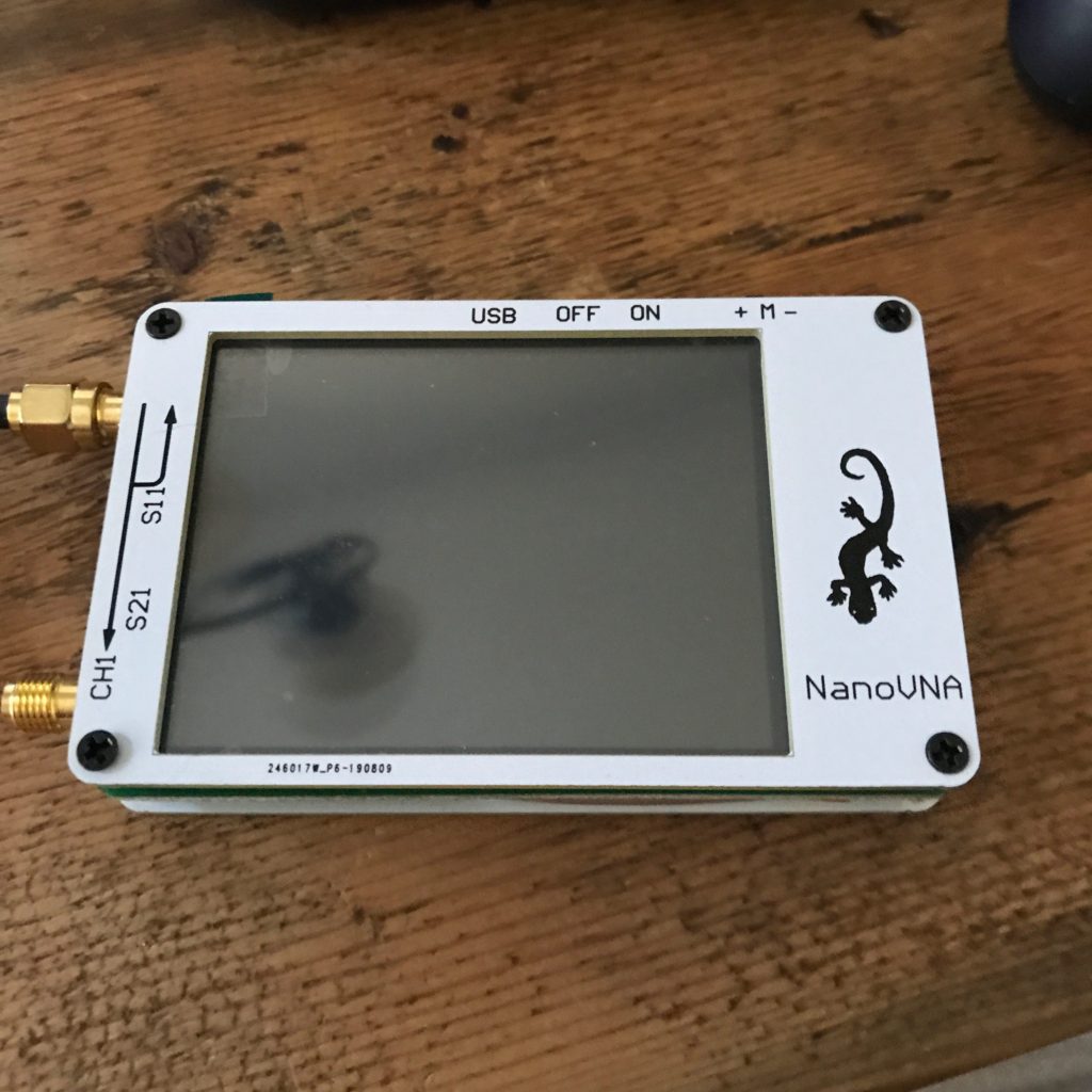
I ordered one for a little more than $50 off of eBay. Mine looks a teensy bit different, having a white case and sporting a stylish lizard on the front.
It came with a USB-C cable to allow it to be charged, a couple of short SMA cables, and a set of three small calibration dongles (one open, one short, one with 50 ohm resistance) so you could calibrate it. The battery was charged when it arrived, so I could power it on quite easily.
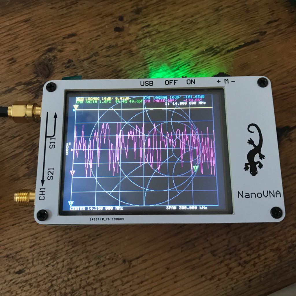
Here’s more or less what it looks like when powered on. I find the overall display to be a bit complicated by default. I need to work on figuring out how to set it up to a less cluttered display. As a ham, I’m usually most interested in using it as an antenna analyzer, which ideally means that I want to sweep it over a range of frequencies, and graph something like the standing wave ratio as it varies by frequency.
In fact, that’s exactly what I got it for. Long time followers of my blog might remember that I tried to setup a small WSPR beacon during the last Field Day, but that a variety of problems kept it from operating. Since then, I’ve actually replaced the burned out Arduino board and had it operating continuously from my back yard, powered by a small solar cell feeding a 7.2Ah lead acid battery through a Chinese charge controller. It consists of a (nominal, never accurately measured) 20mw signal feeding into this whip antenna dipole.
It’s way too low, and I didn’t do much to optimize it. I have an old MFJ-259 antenna analyzer which works fine and is built like a tank, but which is kind of annoying to use. It also doesn’t present any information graphically, and can’t sweep over a range of frequencies itself, so if you want to graph the performance of your antenna over an entire band, you need to basically get a pencil, fiddle the (analogue) frequency generator up and down, dutifully record the SWR (or whatever) over the frequencies, and then graph it yourself.
Yuck, who has time for that?
A friend of mine loaned me his Rig Expert AA600 which works well and will do frequency sweeps and graph the results, but it costs nearly $600, which is far too much for my hobby use.
That’s why I was interested in the NanoVNA. It seemed to be a good gadget that was available for hobbyist money.
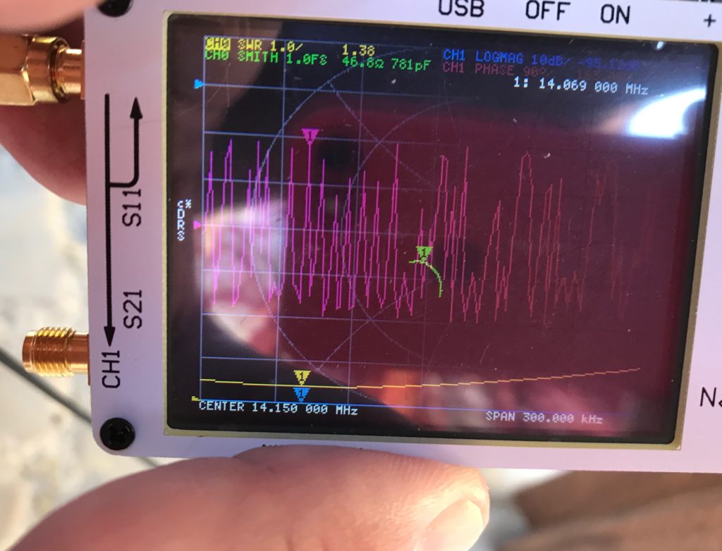
This morning I finally located the necessary pigtail that would allow me to connect the SMA connectors to the UHF connector on my antenna and got it hooked up. I am still a total novice at using it, but I managed to set the NanoVNA to scan the 20m band (from 14.0Mhz to 14.3Mhz) and graph the SWR. Here is the result (with lots of glare from the sun, but hopefully legible).
I haven’t decluttered the display, but you can look at a couple of things. First, near the upper right you can see in white that the frequency of interest has been set to 14.069, which is close to the frequency that I’m operating the beacon at. Going toward the bottom you can see that it says the center is at 14.150 MHz, and the span of the display is 300kHz. Just above it, you can see the tagged “1” inside a small triangle, which shows the current frequency, just above the curve in yellow. This is the SWR measurement. You can see that the lowest part of the curve is very near the “1” target. Nice! At the top of the screen in yellow, you can see that it shows the SWR as 1.38, which seems better than I expected.
Near the center of the screen, you can see the antenna impedance graphed on a smith chart. It is calibrated so the very center of the circular display would mean a purely resistive impedance of 50 ohms. The green line shows the complex impedance plotted over the frequency range. The green triangle marker shows the current frequency, which is very close to the center of the Smith chart. Nice! At the top you can read the complex impedance in green, which is 46.8 Ohms and 781 pF.
All in all, it’s a very cool gadget, and I think it will be a nice addition to my list of ham accessories.
A couple of small caveats:
It has a nice color display that is touch sensitive, but it is on the small side, which makes it hard for a guy with large hands like myself to operate sometimes. It’s not insurmountable, and I’m sure it helps keep the cost down, but I do wish for more dedicated buttons.
The ruggedness of the unit is, well, questionable. In particular, the small tilt switch at the top seems like it would not be great to have kicking around inside your “go bag” and is difficult to operate with gloves. These aren’t fatal for a device you use in the lab (although even there I do have an appreciation for more rugged devices) but you might need to be more careful in the field.
The interface elements are a bit confusing, the fonts and color choices are not super legible, especially for someone with presbyopia like myself.
The calibration accessories I received were not labelled, and it took me a few minutes to figure out which was which.
I haven’t yet explored controlling the NanoVNA from a PC, which might allow for a better user experience.
It does appear that the firmware for the device is open source which means that some of the rough edges that I see might be fixed over time, and may in fact mean that I could write my own firmware that would be more tailored to my own use cases, which is awesome.
Addendum: if you want to see where my beacon has been seen on the WSPR network, you can search for K6HX on the wsprnet.org website, or visit my own custom website which updates every fifteen minutes, and shows all the spots from the previous 24h. I do occasionally get spots from as far away as Hawaii and the East Coast, but today seems a bit more sedate.
I’ve been working on a bizarre little project which involves the very first computer that I ever owned: my trusty old Atari 400. I bought it when I was just 16 years old, and it is probably the artifact of my deep past which is responsible for my career and a heck of a lot of what I’ve enjoyed in the way of geeky hacking.
Without giving too much away, I decided that I wanted to write a simple simulator that would try to emulate the functioning of the sound hardware that is inside the Atari, which all centers around a 4 channel sound synthesizer chip known as POKEY. The details of writing this simulator will probably form the basis of another blog post later, but basically I began with this chapter from the old reference manual De Re Atari.
A quick perusal of the high level description of reveals that the hardware can generate four individual channels of sound, and by setting individual bits, you can change the clock rate at which the sound channels operate to be either 1.79Mhz, 64Khz or 15Khz.
But it doesn’t explain how these numbers are derived.
In fact, the numbers are really only valid for the NTSC version of the Atari 400 and are not specified precisely. This probably doesn’t matter much for most users, but it kind of irked me that I didn’t understand where they came from, and it actually complicated the writing of the simulator.
A bit of digging revealed the following information, which I am going to write down so I don’t have to dig further.
For NTSC systems (the video standard which was common in the United States in those days before HD) these numbers are derived from the NTSC color subcarrier frequency, which is 3.579545 Mhz. A little quick arithemetic will show you that this is 2x the highest 1.79Mhz that POKEY uses to clock sound.
The other two clocks are done by simple pulse division. The nominal 64Khz clock is done by dividing the base frequency by 28, and the nominal 15Khz clock is done by dividing by 114, or at least that’s what appears to be going on. I’m not great at reading the schematics, but this probably reveals some of the details. Assuming the nominal NTSC clock frequency, this makes the “actual” frequencies 63.920Khz and 15.7Khz, respectively.
But anyway, while digging around, I found out that Doug Neubauer, creator of both the POKEY chip and author of the classic Star Raiders game that I spent so much time playing in 1980 has a website where he talks about his days at Atari. Bookmarked here for later consumption. https://dougneubauer.com/starraiders/
I’ve been watching too many YouTube views lately about tool restoration, and as part of my ongoing efforts to equip my home workshop with more tools it means I’ve been hitting more garage sales and picking up a lot more tools which are coated in ferric oxide, and then doing various things to them to return them to working condition. I’ve cleaned up some augers, a couple of crescent wrenches, rusty pliers, screwdrivers, and even a set of four Stanley planes.
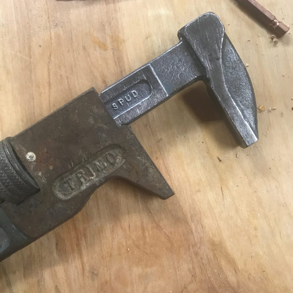
Last week, I got a pretty nifty wrench out of a junk pile for just a couple dollars:
I hit the jaw with a wire sheel to try to get the worst of the rust off instead of using the more gentler Evaporust treatment that I have been using before. It was a bit aggressive, and put some scratches into the flat surfaces, but works a lot quicker. The picture above shows the work in progress, with the body of the wrench still untouched, but the jaw worked for just a few minutes on the wire wheel in my 8″ bench grinder. A few minutes with some 120 and 220 grit sand paper will take out most of those scratches, and leaves the wrench looking pretty nice.
I’ll post a picture when its all cleaned up.
But in any case, one of the things I’ve been interested in is “japanning”. That is the dense intensely black and somewhat glossy black coating on internal surfaces of many old planes. Most of the time, the japanning on old planes is still in remarkably good condition, even a century or more after being created. I wondered what this mysterious material was, and could it be duplicated in the modern workshop. For instance, to finish the wrench above, I thought about perhaps applying that to the inset “TRIMO” and “SPUD” logo (maybe with added white enamel lettering).
And, it turns out, it is possible. This video on Hand Tool Rescue details the material and process that you need to go through.
I thought I’d bookmark this, and at some point in the future I might give it a whirl (particularly if I can find a junk sale toaster oven to do the baking part).
I’ve been on a bit of a woodworking binge lately, no doubt fueled by all the creative and talented woodworkers who have made a place on my YouTube subscription list. I’ve also been slowly acquiring used tools of various sorts, working on a variety of shop projects, and even taking a class.
The “class” is actually just a workshop held for five consecutive weekends held at the local high school where you are free to use their tools and avail yourself of the expertise of the instructor. I decided for my project that I’d like to make a laminated workbench top out of cheap dimensional lumber from the local Lowes. I’d never done such a project before, and as is typical for my projects, I dove in with more enthusiasm than pre-planning. But that being said, I also tend to be fairly thoughtful about such projects, and I learn all sorts of lessons in retrospect.
The workshop gave me access to a large jointer and planer, so I settled on a project that I’ve been meaning to do for quite some time: a heavy workbench top, made from laminated boards and designed to be flat. Like, not just sort of flat, but as flat as I could possibly make it. I didn’t “design” anything. I had a dimension in mind (roughly 2’x5′) and just kind of winged it.
I purchased 20 2x4s from Lowes, which were kiln dried Douglas Fir, for roughly $3 each. I spent a small premium (about $.50 each) to get their “premium” version, which did seem to be overall straighter and have fewer knots than their normal version which costs $2.50. Douglas Fir isn’t the obvious choice for a workbench top. It is fairly soft and fairly splintery, but it has a couple of major advantages: it’s available and it is cheap. I can certainly appreciate using a hardwood like maple for this, but my skills are certainly not adequate to justify spending $1000 on what will almost certainly be viewed as a learning attempt.
I cut all the 2x4s to 64″ and then set to work using the jointer. Here’s where I did things wrong.
The purpose of a jointer is to establish two flat, adjacent sides on a piece of work. In the ideal world, you’d then use the thickness planer to copy that flat surface from these “reference” faces to the opposite.
Here is what I think I should have done, and what I would likely do if I was going to make a second one of these:
Stare at each 2×4, examining it for twist and bow.
Joint the wide face, concave side down, until the piece is flat.
Then carefully joint one (hopefully concave face) by holding the reference face against the jointer, to establish an adjacent 90 degree face.
Now we have two flat faces. It is probably reasonable to use a table saw to rip the pieces to width, holding the jointed face down and the jointed edge to the rip fence on the saw.
Then, finally thickness plane all the pieces with the reference face down in the planer.
Sadly, I did some mistakes. None are going to be fatal, but they definitely made some mistakes and are slowing my progress and decreasing the quality of the final result. In no particular order:
I didn’t check the jointer’s fence for square until I was halfway through. Dumb, dumb, dumb. It wasn’t entirely my fault. Even if I had, the jointer in the shop has a fence which takes to periodic slipping, so it’s likely I would have screwed it up. I tried to do another pass to clean it up, which mostly worked (I missed a couple of outliers) but the jointing job was not perfect.
My jointing technique wasn’t perfect. I suspect that when trying to establish the 90 degree reference face, I didn’t do a consistently great job of holding the reference face against the fence, so even when the fence was perfectly setup, I managed to get a couple of boards through which had some taper and twist.
I suspect I planed some boards inadequately, and some convex bowing remained.
Some of the boards sat in my car for a couple of nights, where the variations in heat may have caused them to warp again, even had I done the jointing and planing perfectly.
I was in a hurry. We really only have 12 hours total workshop time, so I decided to forego planing each board separately, and instead went to glue up (with my imperfect stock) in three sections. Each would be small enough to thickness plane again, to establish the final surface.
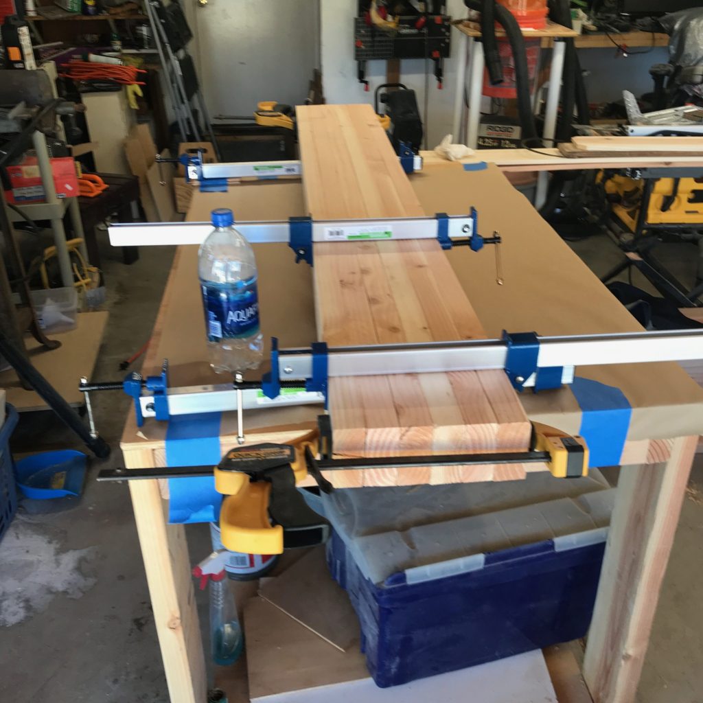
This is where I was after class last week. I decided to proceed with the glue up as best I could, in three different sections: one of six boards and two of seven. I set them up on my assembly table at home. I took some care to use a set of primitive winding sticks to assure that both bar clamps at the ends were parallel, smeared in a ton of glue, and clamped them up.
A dry run of the first section…
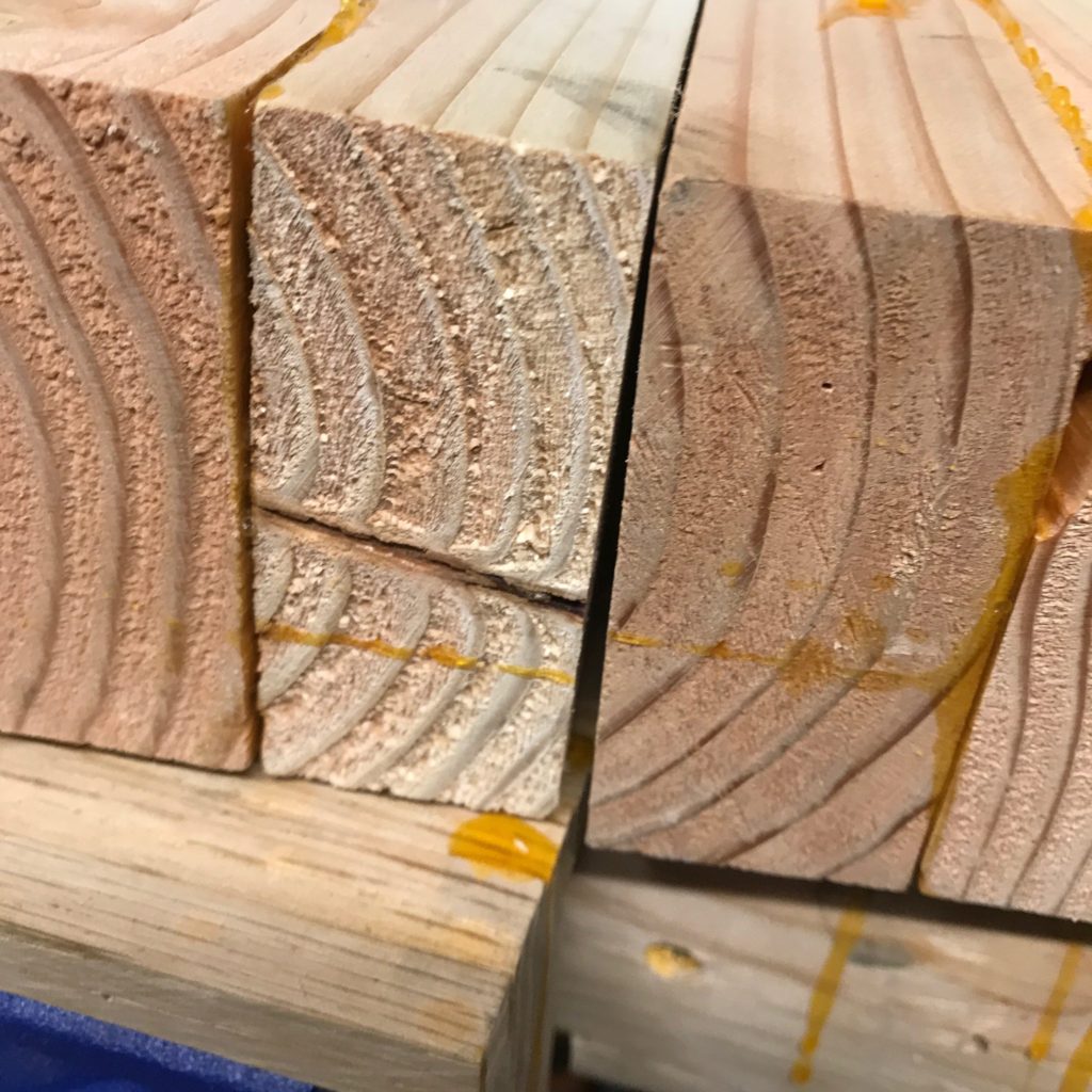
The first section seemed like maybe I used a little less glue than I should have, and despite my best efforts, upon inspection when I was done, I saw that this section had a fair amount of twist (somewhere between 1/16″ and 1/8″) which was faintly annoying. But “once more into the breach”, and on subsequent nights I got the other two sections glued up. They were overalll much better. I did notice that there was still an issue with the first section when I tried to fit the first section to the second.
First section on the left. Note the taper?
Yeah, the edge of my first board has one very poorly cut board which isn’t anywhere close to at right angles with the surface. The first section is pretty terrible.
But I have a plan for salvaging it. Ideally, I could rejoint the section on the wide face and the adjacent edge, but these sections are a little bit wide, certainly not within the capability of my jointer, and not even within the capacity of the workshop jointer, which I’ll only have access to for another week. But where there is a will, there is a way. You can use a thickness planer as a jointer by taking a flat “reference board” and screwing/gluing/taping/attaching somehow the board to that reference sled, and then planing the opposite side. The planer will copy that faux reference face (which is flat) onto the opposite side, and once that side is flat, you can joint the edge and then proceed as usual.
The problem was that was going to take a bunch of time, and I only had a few hours of planer time.
So, I have a new (inexpensive, but highly rated) planer arriving next week.
So, for the class I decided to try to simply stop work on my bench during the class, and we decided instead to put together a simple shop stool that Carmen found on the web using some of my left over scrap Douglas Fir.
It was designed to be made from dimensional lumber with only the simplest tools. We decided to avail ourselves of the jointer and at last clean up the faces. We didn’t do anything (either ripping or thickness planing) to ensure accurate dimensions, but tried to use some care. I made the top out of a glue up that I did as a test before doing my benchtop, which I did thickness plane to a consistent flat thickness.
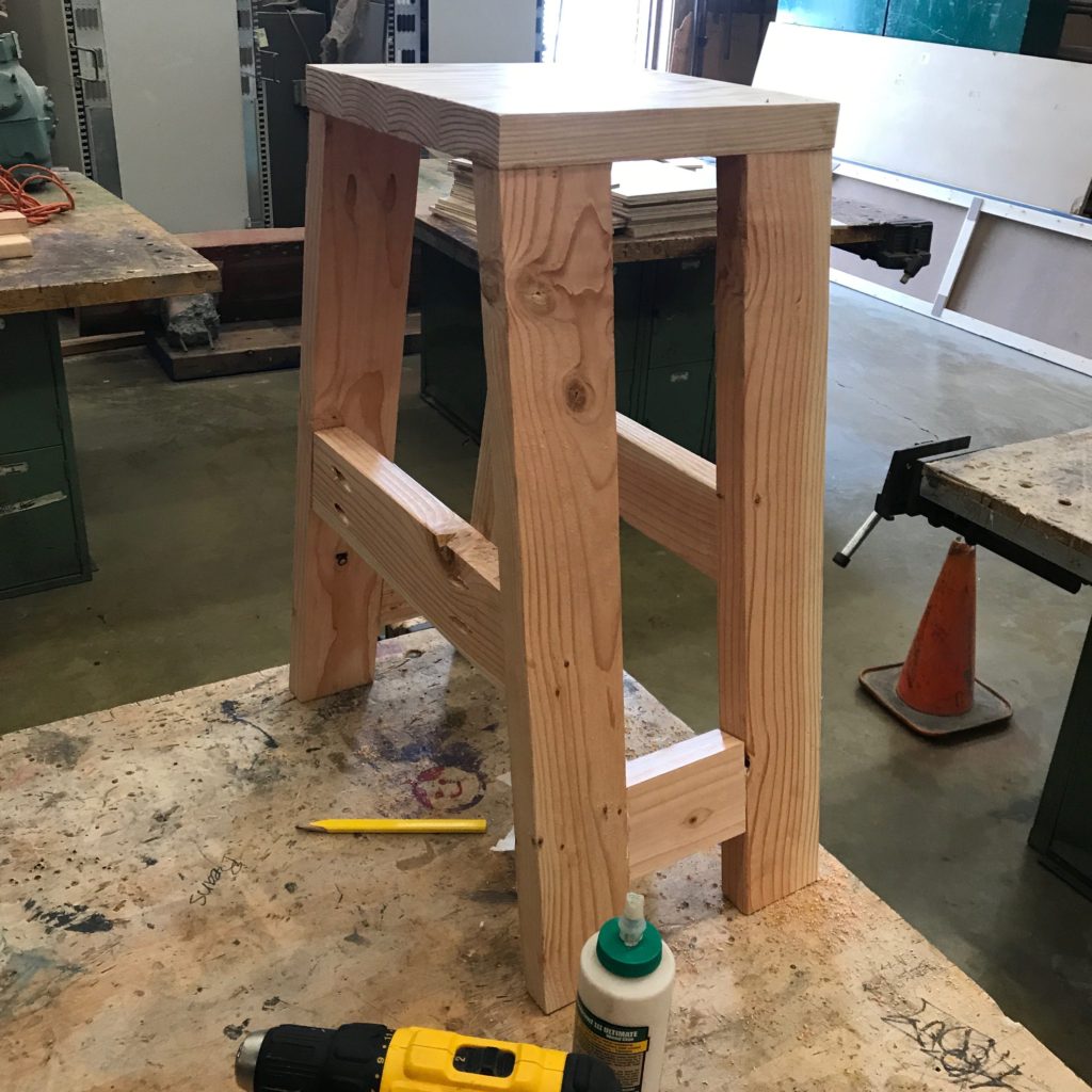
And, two hours later, we had this:
I am actually pretty pleased. We made a couple of minor mistakes. I misread the instructions for the dimensions for the spreader: instead of 14 1/4″ on the short side, I cut it 14 1/4″ on the long side, which means that the stretcher is actually a bit high. We also followed their direction, which had us screwing the legs directly into the seat first, followed by the addition of the cross bar. This actually seems like the hard way to go. It made it difficult (or impossible) to drive the Kreg screws into the side pieces.
The better technique would be to assemble the two side frames first, perhaps by adding a stretcher at the top as well, and then attaching the top last. I’ve also thought that perhaps I should use a half lap joint to attach the stretcher, and avoid the use of Kreg screws entirely.
Anyway, that’s what’s currently going on woodworking-wise in the shop. More projects are coming, as well as others such as the refurbishment of a used bandsaw I picked up at a garage sale a couple of weeks ago. Stay tuned.