Testing Lowrider Z Axis
In my spare time, I'm tinkering together a CNC machine that has mostly printed parts. I'm using the Lowrider V3 design that you can get from V1E engineering. There is actually a V4 design, but I started doing the prints for this last year just before entering my retirement, and am only getting back to it, and thought that there was no pressing need to use the most recent version by starting over from scratch.
Progress has been slow, but I have been inching toward functionality and hope to at least be able to use it as a plotter by the end of July. In the tiny baby steps toward that, I got the gantry mostly assembled with both the X and Z motors installed, and motion was achieved: it moved left and right and up and down. But I thought that I may not have had the Z axis configured quite correctly, so I decided to rig up a basic clamp on the rails to hold my Harbor Freight digital dial indicator that I had, and see what was up.
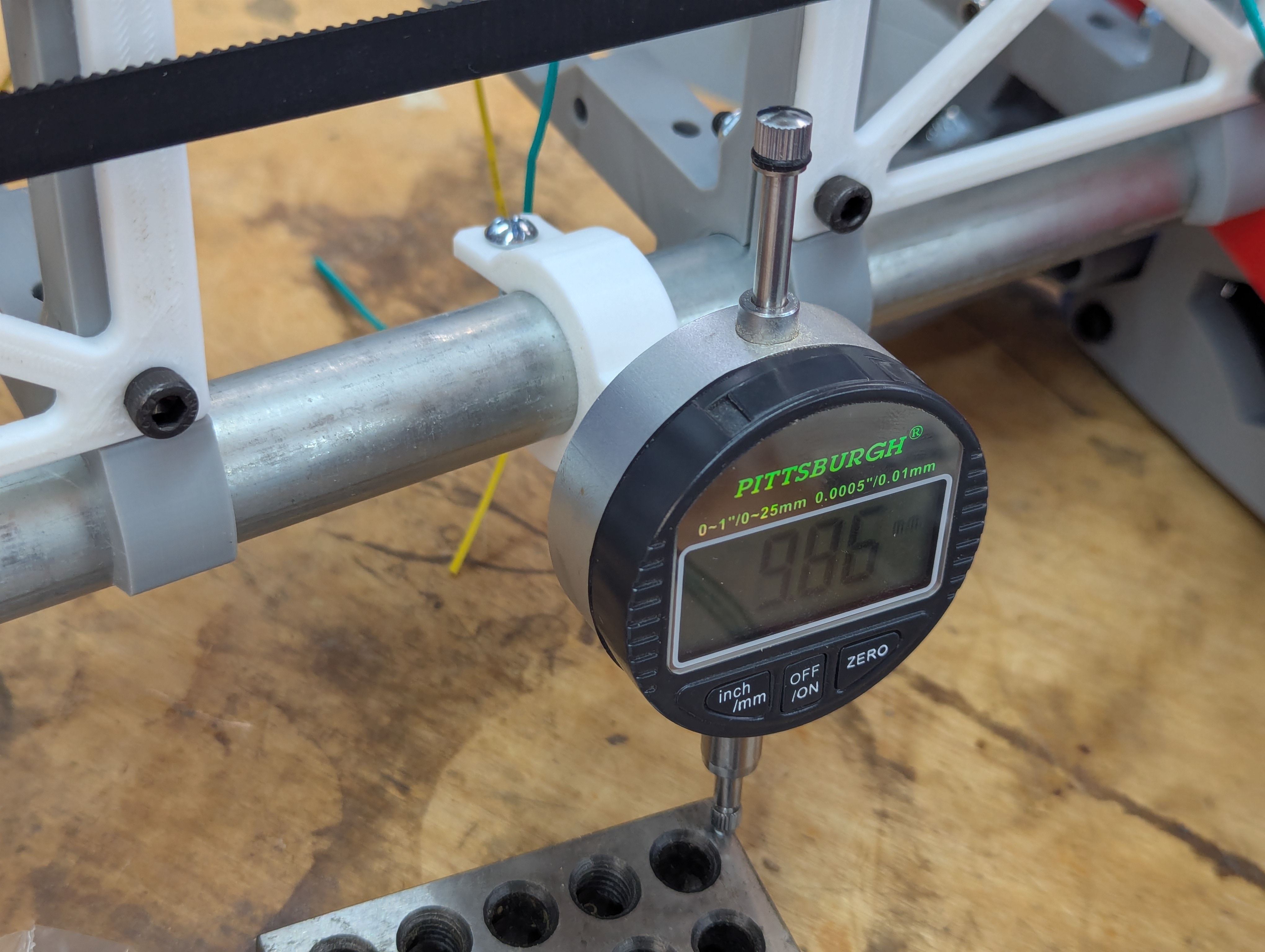
Here is the basic of how it looked.
I quickly discovered two things:
- Yes, I had configured the steppers incorrectly for the lead screws that I had installed. My default configuration seed to specify 200 steps / mm, which was one half what was actually needed. I thought that might be the case, as I swapped out the lead screws that I had (which were 300mm long) for these which were just 150mm long, and their brass nuts were not compatible with each other. I'll go back and double check my order but I don't see this as any serious problem. I modified the config.yaml file that specifies the setup, and now it works reliably.
- I also determined that the right motor was operating intermittently. I rapidly tracked this down to a poor tightening job on the vertical lead screw, and it was slipping. Tightening it back up seemed to restore it to reliable condition.
Here it is with the setup zeroed out (mostly):
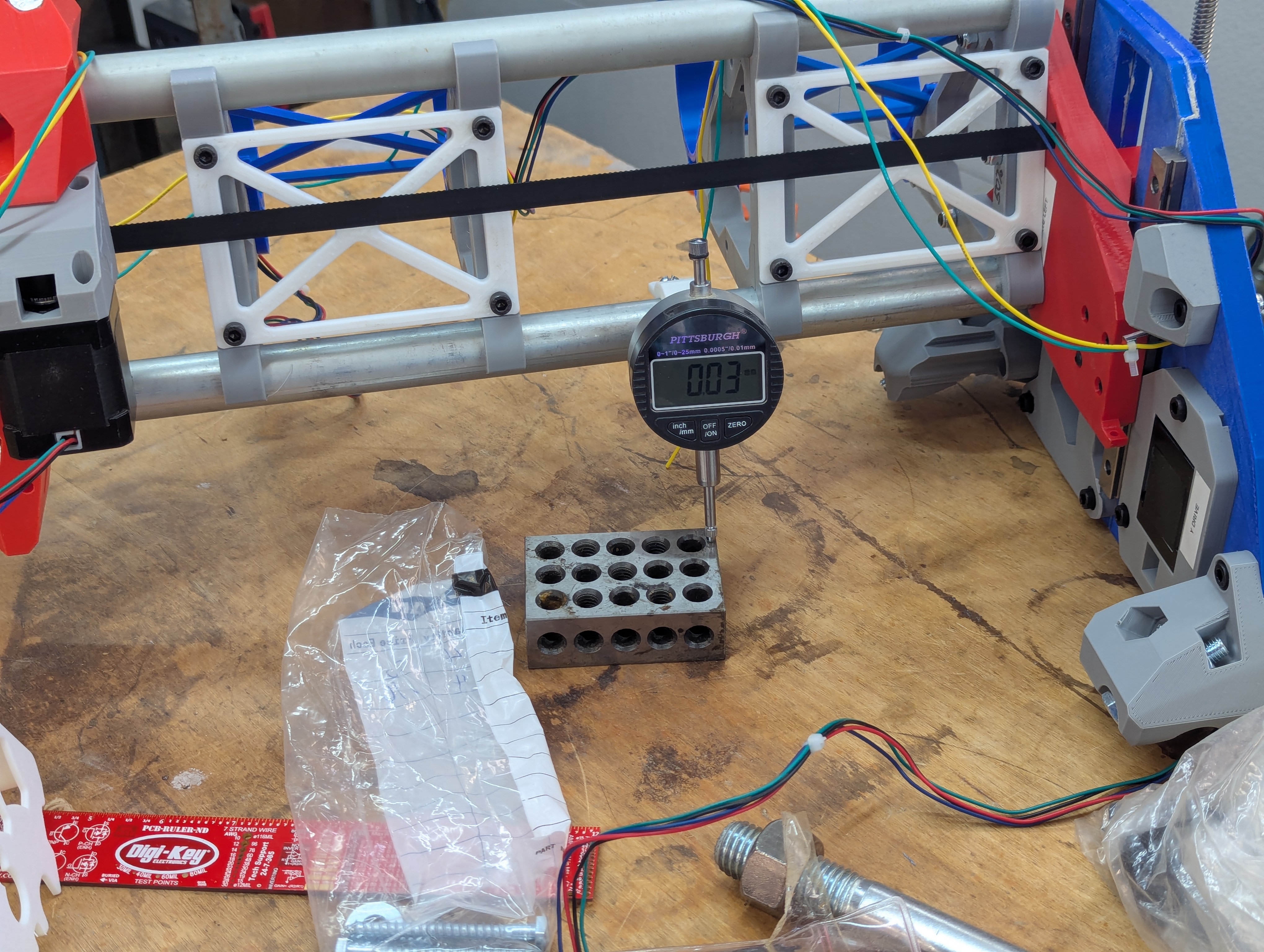
and then after a move of 10mm.
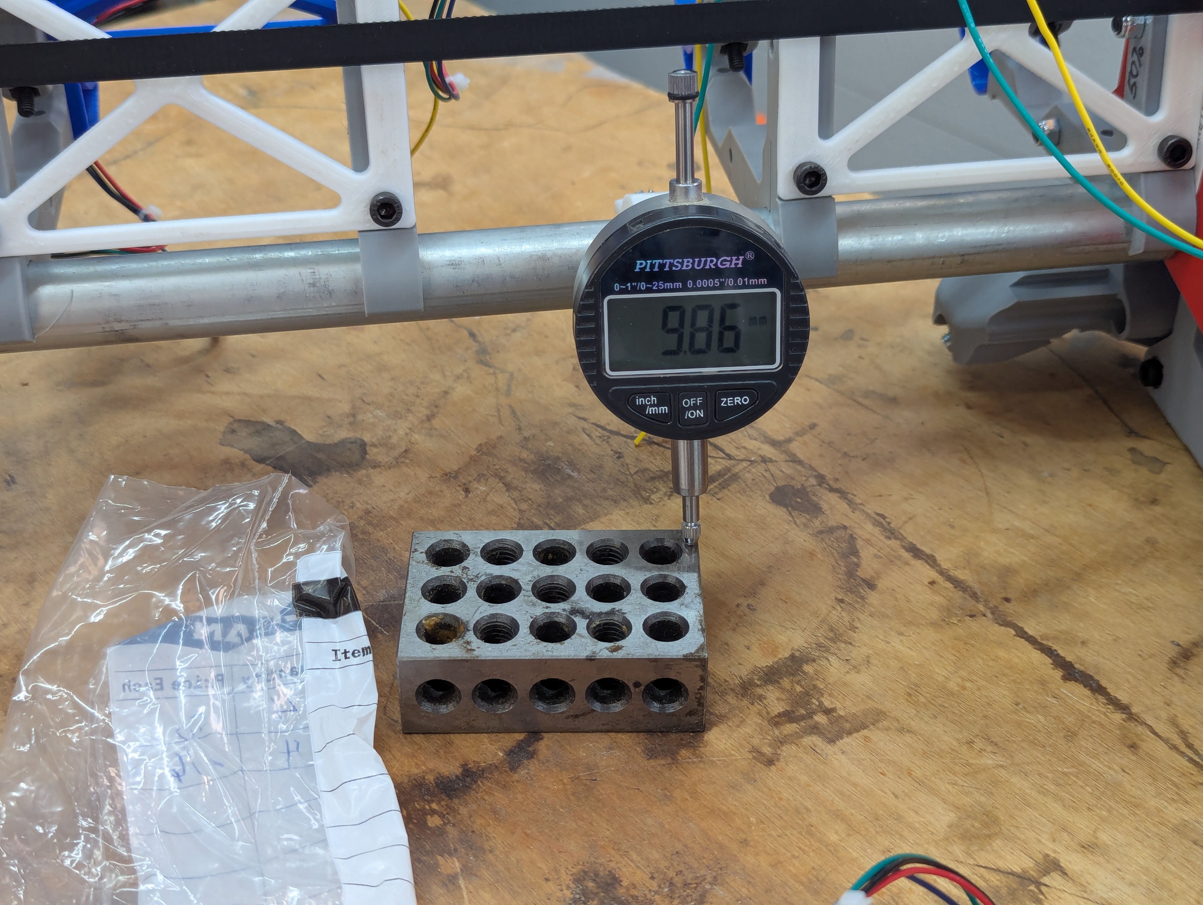
It appears pretty reproduceable. Error seems to be around .16 or .17 of a mm, which is a bit large, and larger than I suspect that even my cheap dial indicator can reproduce. There are likely at least two sources of error that could cause it. Pardon me all you mechanical geniuses out there. Please be aware that I'm a software guy.
The first is backlash error, and while I'm typing here I suspect it would be easy enough to test it: the offset should be fairly consistent regardless of the distance, only whether you've reversed travel. I've got other items to work on today, but I'll double check that when I get back to tinkering.
The second (and perhaps the most likely) is that while the nominal pitch of the lead screw may be reasonably accurate over the short range, it probably drifts a bit over the longer term. Thus, you just need to measure the error over the larger range, and then use it to calculate for this longer term error.
I don't have time to extensively test either of these today, but I'll get back to it in the days ahead. I haven't built anything this complex since my first forays into 3D printing. It's fun.
Hope you all are having a good time.