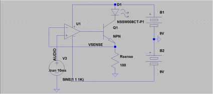
LED Transmitter Schematic
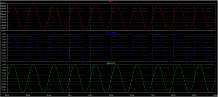
Okay, so here’s the schematic for the LED transmitter circuit as I assembled this evening. I tried to write up an exposition of how it works, but frankly, it pales in comparison to the clarity and completeness of KA7OEI’s page. But here’s the basic idea: imagine that you supplied 1V to the input of the op amp. The op amp will drive the voltage at the base of the transistor so the voltage coming off the Rsense is the same (1V). When that happens, the current through Rsense (and through D1) is just 1V/100 ohms (in this case) or 10ma. And, the current is linear in the input voltage: when the voltage rises to 2V, the current is 20ma, and when the voltage drops to zero, the current is zero. So all you really need to do is take a 1V peak-to-peak audio signal, offset it by 1V (which I didn’t show on the schematic, it’s just inside the audio source node), and it will generate the appropriate current.
It’s very cool, and requires very little math to actually design. And it doesn’t matter much what the transistor is either: KA7OEI’s page uses a power MOSFET, because he is driving a much more powerful LED, but for my purposes, using an ordinary 2N3904 worked just fine.

