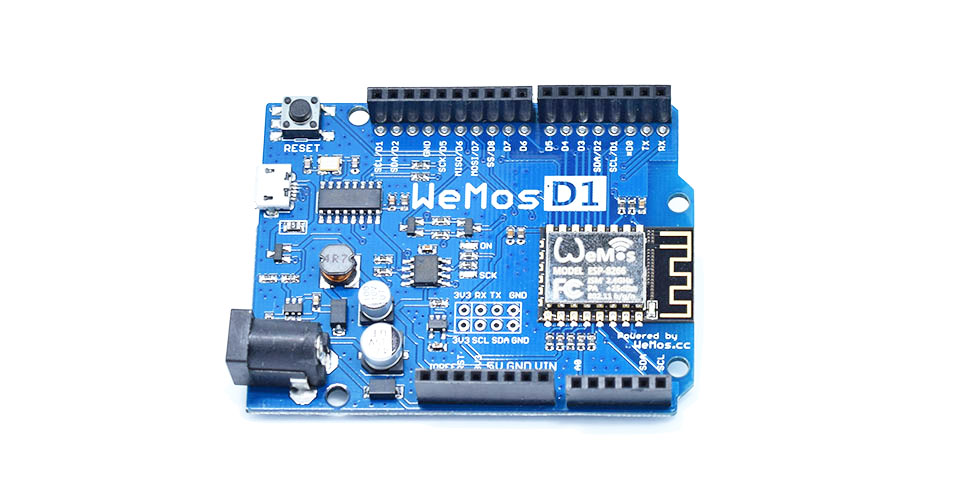
The ESP8266 is an amazing little processor: cheap and capable and (most interestingly) WiFi enabled. I have some of the older “nodemcu” boards that I got for about $7 each, but there are newer alternatives that include up to 4M of flash memory, and a variety of interesting form factors.
I noticed that WeMos was producing these boards which nominally have the Arduino Uno form factor. With a 15% discount coupon from banggood.com, I got three of them on order for under $16. I’ll let you know how they work out. I’m normally not a fan of the classic Arduino shape, but I do have a number of 3d printed cases and bumpers that can be used, which makes them relatively easy to mount and wire up.
If you want to program the ESP8266, you might try using platformio, which makes it easy to use both the native SDK as well as a simpler Arduino based framework. It also supports a number of other embedded architectures, including the Arduino, but allows you to use your own editor and the like to build and organize your code. Worth looking at.
Ken Boak had mentioned on twitter that someone was creating a blinken-lights front end for the simh simulator of the PDP-8, called the PiDP-8, since you can power the entire thing from a Raspberry Pi. Very cool, but not quite available yet. What was available from Oscar is the Kim-Uno, a simulator for the old KIM-1 computer, a single board computer based upon the MOS6502 with a simple LED display and a whopping 1K of memory, first shipped in 1977 or so for about $245. The simulator is incredibly simple: a board, buttons, leds, and an Arduino Micro to drive it all. I went ahead and ordered one, just for kicks.
But you don’t actually need the hardware to play with this: you can get the code running on an ordinary Arduino Uno. So I did. It’s setup to run Microchess out of the box. Microchess is cool because it can play chess in less than 1K of code, and probably was the first commercial game software produced for hobbyist computers.
The Kim-Uno sketch is a little bit odd though. I’ve begun tinkering with it, and cleaning it up a bit. First of all, I thought it was confusing the way it tried to include the 6502 core emulation (written by Mike Chambers). It is written in C, and to merge it into the sketch required a bit of chicanery using ‘extern “C”‘ directives. Bleh, I renamed cpu.c to cpu.cpp, and cleaned that up. I fixed some forward declarations. I uncovered a couple of bugs by paying attention to compiler warnings. It won’t even come close to compiling on non-Arduino platforms, so I deleted lots of conditional definitions. And I generally just tidied things up. Along the way, I checked out the code that Oscar put in to scan the six digit display, which took a lot of pins. As is happens, I had an 8 digit display which used the 74HC595, which I had gotten working before using an interrupt driven display driver. I merged that code in, and now I had a hardware display like the Kim wired to my Uno. Probably refreshes more often than the original, but looks great!
If you follow me on twitter (@brainwagon) you’ve undoubtedly seen a few mysteriously short tweets about experiments I’ve been performing on magnetometers. It’s hard to give any meaningful context in just 140 characters, so I thought I would dump a short overview of what I’m doing here, in the hope that I’ll turn it into a longer post later.
First of all, the inspiration to experiment with magnetometers comes from John R. Leeman’s blog/website. John posted the following video describing how he used inexpensive magnetometers to microcontrollers like the Arduino to teach about the basics of data acquisition and geophysics.
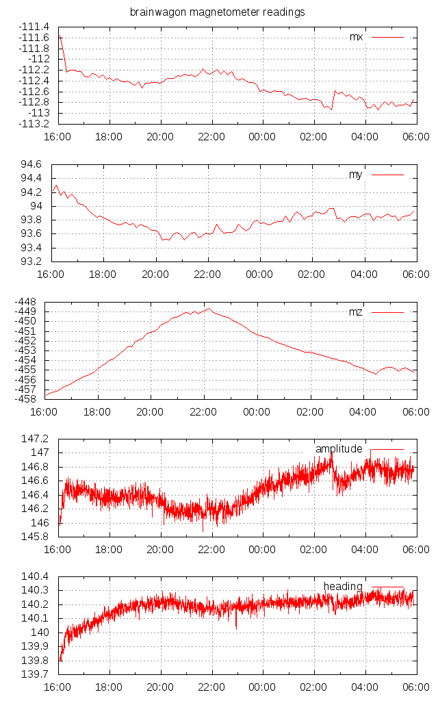
It was inspiring. As it happens, I had a simple 3 axis magnetometer (manufactured by OSEPP) using the HMC5883L chip. So, walking in his footsteps, I wrote some code for my Wicked Device Wildfire V2 board. It’s basically a member of the Arduino family which has built in wifi. My code basically reads the magnetometer and uploads it to the “phant” data logging server hosted at the Sparkfun website. Using the Python programming language, I can fetch the data from this server, and reformat it so that I can visualize it with gnuplot. For instance, here’s the smoothed data (mx/my/mz) and the computed amplitude and heading.
I’m really only just now trying to understand what the data actually means, and how the sensor is affected by things like temperature. This sensor is currently in my upstairs bathroom, which probably has a fairly wide temperature swing, is not level, and is probably closer to nearby metallic options than optimal. I’ll be letting this go in its current state to see if I can spot the diurnal (daily) variation in the heading. I suspect that most of the change in amplitude is actually due to changes in temperature. When I get a chance later this weekend, I’ll reset the device, and add a temperature sensor (probably a DS18B20) and record that along with the magnetic data, and maybe do some work to calibrate the sensor better.
I really like John’s site, and he also co-hosts a nifty geology podcast called the Don’t Panic Geocast. Definitely worth listening to, and inspiring me to learn more about geology, a subject that I admit I know relatively little about. Good stuff!
Yesterday I just had a few minutes to hack around, and I decided to marry a sketch that used the TinyGPS++ library to the clock display that I had working the other day. I’ve been hopping back and forth between the Arduino and the Teensy LC as a development platform. Since I still had the display hooked up to an Arduino (actually the Sparkfun RedBoard, my favorite compatible) I decided to hook up the GPS to the RedBoard as well, to serve as the time source: the Arduino would wait until the GPS acquired a lock, and would then begin displaying the time.
Because the Arduino Uno (and RedBoard) have only a single dedicated serial port, the usual way to connect a GPS is to create a SoftwareSerial port using (say) pins 5 and 6. So, that’s what I did initially. It worked, but I found that whenever you did a Serial.read(), it caused a minor glitch in the timing of the refresh. At the beginning of each second, when the GPS squirts a substantial amount of text to be received, the entire clock display noticeably flickers since the Serial.read() messes with the timing of interrupts (presumably, by blocking them for a short but significant period of time). Bleh.
In the end, I ended up hooking the GPS pins to the hardware serial port on pins 0 and 1. The problem is of course that then the pins are unavailable for other uses, such as printing status back to your USB port, or (notably) downloading new code. I had to disconnect the GPS, flash the software, and then hook up the GPS again. The result was nice and smooth, no flicker.
A much better solution is to use a small board like the Teensy LC or Teensy 3.1. They each have three dedicated hardware serial ports in addition to the normal Serial device which can communicate back through the USB port. The Teensy 3.1 even includes hardware FIFO buffers, which will enable even more flexibility.
When I get some free time, I’ll probably include intermittent display of both latitude and longitude. Because I can, that’s why.
In a previous post, I wrote some interrupt driven code to refresh a multiplexed 8 digit, 7 segment display. Every 2 milliseconds, the Arduino triggers an interrupt, and then clocks out sixteen bits to a pair of chained 74HC595 shift registers, and then returns. That displays a single digit. The next interrupt displays the next digit, and so on until all eight are displayed. Because of persistence of vision, you don’t perceive any flicker, and you get a nice display.
Two things bothered me about the previous code: on a standard Arduino, it used about 18% of all available CPU cycles to do this refresh. That’s a lot of time to dedicate to just display. It’s not hard to see why: the code calls digitalWrite both directly, and because the shiftOut call also uses digitalWrite.
The problem is that digitalWrite is slow, really slow.
The reason is that while digitalWrite is slow, it’s actually doing an awful lot. At the hardware level, all the digital pins of an Arduino (which are numbered 0…13) are individual bits in one of several eight bit hardware ports. These ports are really just memory addresses. They have both a data direction register (which tells you whether each bit in the port is an input or an output) and a data register, which for inputs tells you whether associated pin is high or low, and which you can turn on individual bits to set outputs high or low.
On the Arduino Uno, pins 8-13 are attached to the lowest bits of the PORTB. You can assign byte values to PORTB, and the associated outputs will get driven high or low, all in one instruction. You can even set multiple bits at the same time,
which is impossible to do with digitalWrite.
So, why use digitalWrite?
It’s more portable. All Arduinos have pins 0-13, but some map them to different underlying PORTS (Arduino Megas for instance have more I/O ports, and a different mapping). By using digitalWrite, you don’t need to know which port corresponds to which pin, that’s all part of the library. The Teensy LC that I was testing with yesterday doesn’t even have the same underlying chip architecture, but the libraries to emulate the Arduino all behave perfectly, and I don’t have to change even a single line to get it to work with the Teensy. That’s pretty cool.
But it is pretty slow.
My testing yesterday showed that on the Arduino Uno, using digitalWrite meant that the critical part of the interrupt routine took 320 microseconds. The Arduino Uno runs at around 16Mhz, and can basically run one instruction per cycle, so that means it is taking about 5120 instructions just to clock out the sixteen bits into shift registers. Each bit requires about three output bits to get toggled, so that means that each toggle is around 100 instructions long.
I knew I could do better.
As I said, pins 8-13 are the low bits of PORTB. By directly accessing those bits, we can speed things up alot.
Without further explanation, here’s the old, short, portable code that calls digitalWrite and shiftOut routines:
A couple of days ago, I wrote about experimenting with a little Chinese 8 digit, 7 segment LED module that is driven by some 74HC595 shift registers. My initial experiment in driving it with the Teensy was successful: I got a nice, steady display with a simple interrupt driven scheme which displays each digit for two milliseconds before moving on to the next. But I wondered what percentage of my total time was actually being spent refreshing this display. In particular, how fast was the interrupt routine?
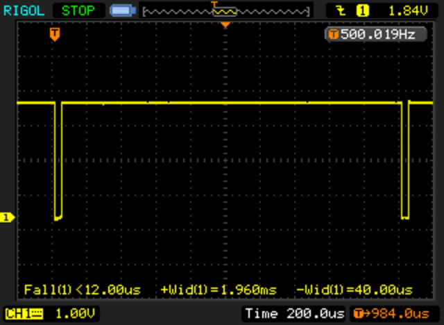
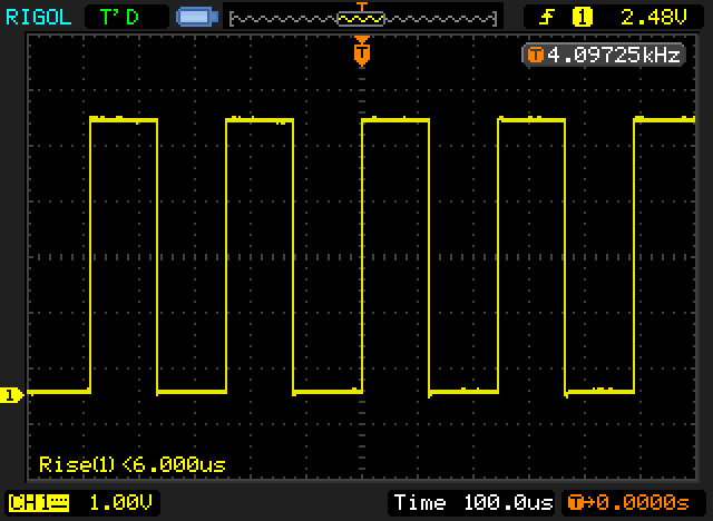
Most of the time spent in the interrupt routine is presumably spent in serially clocking out the individual bits to the shift register, using the Arduino library function shiftOut. I thought about adding some timers and computing what the time left, but this morning, I realized that I could use my nifty Rigol scope to figure out how long it took, by looking at the LATCH signal. Before clocking the data, the LATCH signal is brought low, and then afterwards brought high again. There are a couple of instructions on either side, but it’s not a bad approximation.
When I got home, I hooked up the scope.
Nifty! The total time accounts for 40 microseconds out of every 2000 microseconds, or about 2% of the total runtime for the Teensy. Nice! Works great. My guess is that it would be significantly more as a percentage with a traditional Uno. Perhaps I’ll try that out soon.
Addendum: I installed the same code on the Sparkfun Redboard (an Arduino Uno clone, which is an ATMEGA328 running at 16Mhz). With identical code, I used the same setup. The interrupt routine runs in about 360us, about 9x slower, consuming about 18% of the available CPU cycles. If you double the period to 4ms, you could halve this, but I find that the strobing of the ~33hz display to be slightly too much for me.
A few weeks ago, I was scanning the Deal Extreme website, and ordered a few different LED displays, not because of any pressing need, but because I wanted to have some display options available if I needed some for a project. I was especially interested in cheap LED displays. One of the ones I ordered was this 8 digit, 7 segment display, which seemed to have a five pin interface. Without thinking about it too much, I went ahead and ordered it.
Today, they arrived. Like a lot of things that come from dealextreme, this one had been shipped somewhat haphazardly: the right angle header pins were significantly bent, but a little gentle prodding moved them back into place. I then spent a few minutes trying to decide what the module actually needed.
Unlike the modules I’ve had previously based upon the TM1637/TM1638/TM1640, these modules did not have a controller onboard that could latch all the segments and hold values. Instead, this board has 2 8 bit shift registers (namely, the 74HC595). Basically, one shift register controls which of the 8 digits are powered up (a high value in the 8 bit word indicates that the corresponding digit has a power on its cathode (which is common to all the segments of the LED) and the other 8 bit word tells it which segment is turned on (actually, it’s inverted: a 1 indicates the corresponding segment is off).
But here lies the rub: you only have 8+8 control lines, but you have to control 56 (actually 64 if you include the decimal points) segments. The way you get around this is to display a single digit at a time, but only do it for a short period of time. If you flip between digits fast enough, your persistence of vision will merge them into a consistent display.
The usual way to do this with an Arduino would be to use the shiftOut statement to clock the data out on some serial pins, and then call delay (or delayMicrosecond) to wait a bit, then shift the data out for the next digit, etc… But that makes the loop() difficult to write: you have to interleave both the display and all the other work that you have to do, with careful attention to timing.
There is a better way: interrupts. In particular, I used the TimerOne library (available on the Teensy as well as the Arduino libraries) to setup a timer interrupt. The idea is to contain a display buffer of 8 bytes, one byte per digit, which specifies which of the 8 segments is on. When the interrupt occurs, it clocks out the cathode and then the segments for the specified digit as quickly as it can, and then increments the display digit by one, wrapping around if necessary. Because this happens in an interrupt, it means that display happens without any real use intervention. When you want to change what is displayed on the display, you just change the contents of the segment buffer and then the interrupt fires next time, the appropriate digit will
be displayed.
The basic code worked the first time I typed it in (modulo plugging jumpers into the wrong pins on the Teensy, and with the digits occurring in the reverse order than I desired). A moments tweaking yielded this nice, steady display:
I’ve decided that rather than posting code fragments embedded here, I will instead post links to a github repository that holds the necessary code. As I extend and make improvements, you’ll be able to get updated code there.
I was working on some additional software to power my nascent WSPR project. I’ve been thinking that rather than using an Arduino, it would be better to use the Teensy, so I’ve been experimenting a lot with the Teensy LC. My idea was to wire up my Ultimate GPS and an I2C based DS3231, and then write a sketch that powers up the GPS, attains a fix, and then uses the time to set the time on the DS3231. It then will periodically wake up the GPS and check the time as reported by the DS3231 against the GPS.
But I’m having some difficulty. The GPS part works just fine, but when I try to do the first write to the DS3231 to set the time, it occasionally hangs. The way these libraries are written, the writes never time out, and the exchange grinds to a halt.
I’m not sure what’s going on here. Could be a bug/issue in the library, or something having to do with the Teensy Wire library, or the pull-ups. The rise times seem very slow.
I’ll keep playing around to figure out what the deal is.
Addendum:This seems relevent but the code is only for real Arduinos, and probably needs some tweaks to work with the Teensy. I am curious as to whether the delay itself may be enough to help.
Yesterday, I got a small 4 digit, 7 segment LED display board in the mail from dx.com. Cost was around $3 shipped, and the module uses a 4 pin interface (power, ground, clock and data). Originally, I thought it was I2C, but like other modules I have received based upon chipsets made by Titan Micro (using the TM1638 and TM1640) it looks superficially like I2C, but doesn’t use the open collector bus and addressing scheme of I2C. You end up clocking commands to the board using two dedicated pins.
The driver that I’m using comes from here. It is based upon the driver from avishorp, but includes support for the colon that separates the two pairs of digits on this display, which I wanted to allow blinking to help indicate that the clock was running. This was my example sketch, which is completely unremarkable. It doesn’t set the time from a real source, I just hard coded it to set the time to a specific constant near when I compiled it.
void setup() {
Serial.begin(9600);
// put your setup code here, to run once:
setTime(1432823831UL);
display.setBrightness(0xF);
}
boolean colon = true ;
void loop() {
// put your main code here, to run repeatedly:
int t = hour() * 100 + minute() ;
display.setColon(colon);
colon = !colon ;
display.showNumberDec(t, true);
delay(1000) ;
}
[/sourcecode]
It works reasonably well.
Addendum: I received this tweet:
@brainwagon A cute RTC library hack I learned while doing my little toy clock: rtc.adjust(DateTime(F(__DATE__), F(__TIME__)));
Not a bad little trick to archive. Instead of using the Time library, you need to use the RTClib library. I modified my program above to do it. Here’s the new version:
void loop() {
DateTime now = rtc.now() ;
int t = now.hour() * 100 + now.minute() ;
;
display.setColon(colon);
colon = !colon ;
display.showNumberDec(t, true);
delay(1000) ;
}
[/sourcecode]
Note: the time gets set to the time when the code is compiled. If you compile and install it, it will likely be a couple of seconds off. And when the Arduino gets reset, it will get reset to that same time. This is most useful in setting the time on an external time keeping module.
Previously, I wrote about a project I called the Big Box O’ RF. I’ve shifted goals a bit, and done some experimentation, and have changed some of my goals and approach.
First of all, I’ve changed the goal a bit. Instead of being a piece of test equipment, I’m actually more interested in using it to implement a beacon transmitter. It’s been quite some time since I have done any QRSS (slow speed Morse) or WSPR (Weak Signal Propagation Reporter) but I still find it to be a pretty interesting thing to do. What I’ve wanted to have for a while was a dedicated beacon transmitter that didn’t require the cooperation of my laptop and FT-817 to send out a modest signal. It seems to me that this totally doable mostly with parts I have on hand.
Goals:
Output power between 250mw and 500mw
Controlled by an inexpensive microcontroller. While the Arduino would be an obvious choice, the Teensy LC or Teensy 3.1 are as easy to program, and offer some interesting improvements for similar cost.
Able to integrate multiple methods to keep accurate type of time. Initial prototype will probably use the Ultimate GPS I’ve been playing with. Alternatives include clock boards based upon the DS1307 or DS3231, or synchronization via Wifi/SNTP (almost certainly using the ESP8266).
Able to support multiple modes: at least WSPR, DFCW, and Slow Feld.
LCD panel to display information. Text based interface supplied via USB, allowing you to change message, frequency, timing, etc…
RF generated by my AD9850 module.
I’ve been tinkering with most of the modules independently, making sure I can interface with each of them. They all seem to work fairly well. As soon as I find an appropriate box, I’ll start getting them put together. I’ve built a harmonic filter for 30m (where I plan to do most of my operation). I need to work on the amplifier chain, as well as a little transmatch (I don’t want to dedicate one of my antenna tuners to this operation either).
One of the things that I really like about the Teensy LC (besides its low price) is that it has three hardware serial ports. Hardware serial ports are just nicer than the SoftwareSerial ports that you see on the ordinary Arduino platform. While the latest support for SoftwareSerial ports on digital pins work reasonably well at low baud rates, they aren’t especially good or reliable at higher baud rates. The Adafruit UltimateGPS I have supports data output at 10Hz, which requires serial rates of 115200, which isn’t especially reliable.
But I’m still inexperienced with the Teensy. To test my understanding, I wrote this little program for the Teensy LC, after hooking my GPS up to pins 0/1 as RX/TX. Note: the Serial object does not route to any of these three outputs: the Serial object is a distinct USB object that is not mapped directly to digital pins.
This was also an attempt to test the TinyGPS library with the Teensy LC. It worked the very first time I got it to compile.
I’m definitely leaning toward using the Teensy (either the cheaper LC version, or the more expensive but more faster/more capable 3.1, which includes FIFOs for serial ports) on my WSPR project.
[sourcecode lang=”cpp”]
// __
// / /____ ___ ___ ___ __ _________ ____ ___
// / __/ -_) -_) _ \(_-</ // /___/ _ `/ _ \(_-<
// \__/\__/\__/_//_/___/\_, / \_, / .__/___/
// /___/ /___/_/
//
// On the Teensy LC, there are three hardware supported serial ports.
//
// Port Rx Tx
// ——-+–+–+
// Serial1| 0| 1|
// ——-+–+–+
// Serial2| 9|10|
// ——-+–+–+
// Serial3| 7| 8|
// ——-+–+–+
//
// It appears (as yet unverified) that these are distinct from the serial
// port which is connected to the Serial object. This program is designed
// to test that theory.
I hooked up my new DS3231 clock module to an Arduino that was being fed with the one pulse per second input from a locked GPS, and counted the number of pulses from each. In 3170 seconds, the clock module generated 103874565 pulses, for an average pulse per second of 32768.0015773 pulses per second. That’s really good, only about 2 seconds per year. Of course this was a short term test, under relatively stable temperature conditions, but still, I’m highly impressed. I’m thinking that using this to drive my WSPR radio beacon is likely to work out very well.
As I mentioned in a previous post, I was not enormously satisfied with the accuracy of the DS1307 clock module that I got from China. It was hard to argue with the less than three dollar price tag, but I was hoping that the accuracy might achieve 20ppm (less than two seconds of drift per day). My measured drift was over ten times that, about 25 seconds per day. Ungood.
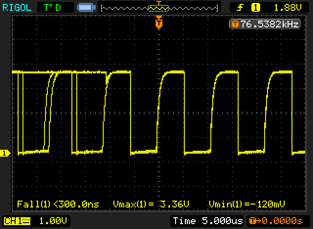
It seems to have a dedicated 32KHz output, but it doesn’t run when solely on battery power.
The rise time of the 32kHz signal is pretty slow.
The duty cycle of the 32Khz signal is significantly below 50%.
The frequency as reported by my (not terribly accurate) oscilloscope’s built in frequency meter seems very close to the nominal 32768 Hz signal.
When I get time tonight, I’ll test it against my GPS and see what really works. My initial impression? Positive. If you care about even reasonable accuracy, paying a couple of bucks more for a clock module will probably be a good idea.
My tinkering with using the Adafruit GPS as a time base has yielded some results. I’m still getting a few spurious interrupts when I feed my buffered PPS signal into the interrupt pin on the Arduino, but they are relatively few and far between (and quite regular in appearance).
A few short notes, followed by my conclusions.
The PPS signal from the GPS is a pulse at 1Hz, which remains high for 100ms and then drops back to the ground state. The voltage peaks out at 2.8 volts.
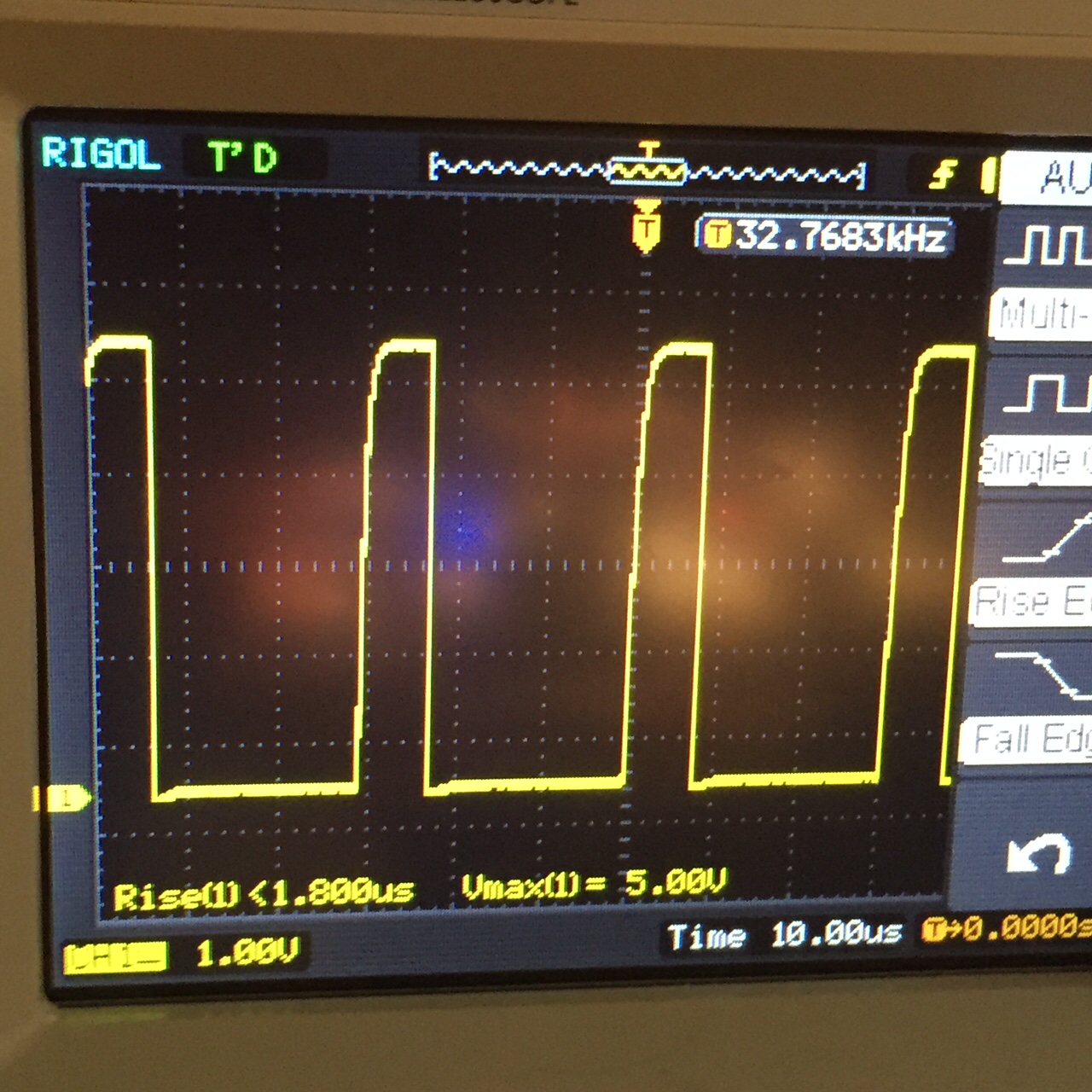
The SQ signal from the Tiny RTC board is a (nominal) 32768 Hz signal. it’s a 5v square wave, with a 50% duty cycle.
(This screen capture is actually for a 4096 Hz signal which I experimented with earlier, but have since changed to a 32768 Hz signal).
I wrote this code to use the 1PPS as a signal to count the number of clock pulses per second.
void
loop()
{
for (;;) {
if (dirty) {
dirty = false;
Serial.print(pps_cnt);
Serial.print(" ");
Serial.println(clk_cnt);
}
}
}
[/sourcecode]
I encountered a couple of odd problems though.
Initially, I seemed to be getting spurious calls to the pps_interrupt. In particular, while the PPS signal was high, transitions of the CLK signal seemed to trigger spurious calls to pps_interrupt. Thus, I’d get about 3270 additional calls to pps_interrupt.
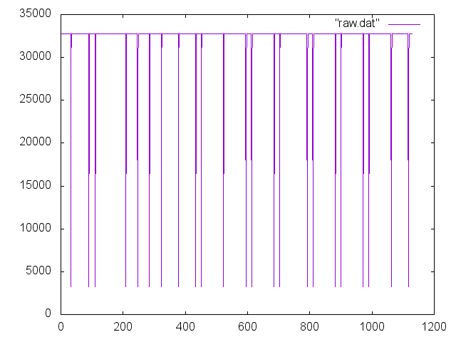
I was suspicious that perhaps the 2.8v PPS signal was causing some problems somehow. I constructed a simple inverter (1K ohm resistor into the base of a 2N3904, with a 10K resistor connecting the collector to the 5v supply, output tapped below the resistor). When I hooked up the output of the inverter to the Arduino interrupt input, I got much better results, although there still seemed to be an odd transition or two when the PPS swapped state. You can see the result in this graph:
The low end of measurements are all approximately (nearly exactly) 10% of the average value. In looking at the raw data, you can see these low values are followed by a value which is 90% of the average value: in other words, they sum to the average value, which indicates that the interrupts were spurious, and likely happened when the pps signal returned to the HIGH level (remember, we now have a buffer inverter in place).
If we ignore the spurious interrupts, we can calculate the accuracy of the DS1307.
Using this data, we find that the clock is running a bit fast: there are 32777.652 transitions per second, instead of the nominal 32768. If you multiply this out, you get that the DS1307 runs about 25.44 seconds fast per day. That’s pretty miserable, about 300ppm. I’ll double check the math again, but so far, I’m suspecting that perhaps paying more than $3 per module would be fruitful if accurate time keeping is required.
Greetings readers. I’m hopefully wishing there is still more than one.
This weekend was the Bay Area Maker Faire 2015, the 10th incarnation of an event which has become increasingly (even frighteningly) popular. I’m tempted to channel Yogi Berra, who said “Nobody goes there. It’s way too crowded.” Anyway, I got out of my house around 9:00AM, with the plan of parking at one of the offsite parking lots and shuttling in. It took me about an hour to get to the Oracle lot on 10 Twin Dolphin Drive, and there were already probably six or eight busses lined up, but probably a thousand people lined up as well. As it happens, it took slightly more than an hour to make it onto a shuttle, drive in and enter the gates. Bleh. Not the most fun, but I had a good nights sleep the night before, so I was mostly in good spirits as I entered the park.
It was very crowded. I was by myself, so I just started wandering. When I go to these things, I am mainly looking for three things:
Projects that inspire new projects.
Cool new products, especially inexpensive dev boards and gadgets for future projects.
Cool artwork that I haven’t seen before.
Sadly, I didn’t see a ton of projects that made me think of new projects, but there were a couple. I had a nice chat with Ben Krasnow who brought some low-tech versions of his excellent rheoscopic coffee table, which were just plastic cells that rotated on a lazy susan. You’ve probably seen identical gadgets in science museums. Fluid flow is always interesting. He said the instructions were already on the Make Magazine site, but I forgot to copy the url, and didn’t find it. He also said it would be in the print edition sometime soon.
I had a nice chat with Erin Tomson of Modulo Labs LLC. She’s a former Pixar colleague, who has gone off and created Modulo, a set of pluggable programmable modules that can be used to assemble modules in a tiny, secure network, without the hassle of routing jumper wires on breadboards. (In fact, a system like this would have prevented a lost hour of my time tonight, I’ll tell that story below.) It’s a very slick little system, and I’d like to see something like this take off. I can particularly see this as useful in education.
Check out her Kickstarter video.
I particularly like optical gadgets like telescopes and microscopes. My buddies Rich and Dave from the Chabot Telescope Makers Workshop were there, grinding away and answering questions about telescopes. Nice to catch up with them. They said that quite a few people came up to them and asked “So, you guys sell telescopes?” Sigh. This is the Maker Faire. If you are in the North Bay and want to learn how to build a telescope, click on the link above, and think about attending one of their free workshops (every Friday!).
I like projects which reuse camera phones, and this microscope project seemed pretty cool. They had a little gadget that allowed you to swap out three different lenses to get different magnifications. Their system seemed pretty cool, but the basic idea is pretty simple (in fact, it’s basically a version of Antonie van Leeuwenhoek’s first microscopes, but instead of holding it close to your eye, it’s held close to your cell phone, which can use nifty features like zoom and exposure adjustments, and can of course record video and stills. I should design such a gadget myself.
I also had a nice chat with Alan Yates who was demonstrating some “Lighthouse” technology that he’s been working on at Valve. The basic idea is to create a set of “beacons” that can be scattered around an environment, and a sensor that can (for instance) be mounted on a VR headset and can be used to figure out the position and orientation of the headset with high accuracy and low latency. I don’t have a link for this work yet (did I miss it, Alan?) but when I do, I’ll try to update it.
That was kind of it. I did poke my nose into various people experimenting with aquaponics, which I find interesting. I had a brief chat with the creators of Chip, the $9 computer currently on Kickstarter (I hope to have more information on that soon, stay tuned.) I didn’t spend much time in the “Dark Room”, the noise and flashing gives me a headache. I did spend some time looking at the various gardening and bee keeping exhibits.
And, I did pick up some new gadgets. Here’s a short video of my purchases, along with some links to the various items mentioned.
A Spark.io Particle Photon Kit Spark.io has changed their name to Particle, and then did a deal with Sparkfun to build additional add ons and distribute the Photon. I don’t know a lot about the Photon yet, expect some posts about it in the future.
A little wireless keyboard from dfrobot.com. Hooked it up to my Raspberry Pi in my living room, and it seems to work pretty well. DFRobot appears to have their own line of Arduino clones, including ones that do Bluetooth Low Energy at fairly reasonable prices. Might be worth checking out.
And that’s about it. If anyone thinks I missed something super cool, drop me a comment below and I’ll check it out.
Today, I had a bunch of chores to do, but I did start to play around with my AD9850 project a bit more. Since I spent so much time driving around yesterday, I had lots of time to think, and realized that the code the determined the tuning word (the 32 bit value used to select the frequency of the oscillator) was probably going to not work properly, since it used floating point arithmetic, and that probably didn’t have sufficient precision to do the calculation the way that I had coded. Indeed, when I got home, I hooked up and Arduino and found that I was not getting the sub-Hz spacing that I requested. I played around with the math a little bit, and got it working better, and then set it up and started it going. I had the output of the AD9850 going into my oscilloscope, so I could monitor the waveform.
And it was glitchy. Intermittent. Not working properly. Had I made a programming mistake?
I spent the better part of 45 minutes trying to understand how I had broken the program. Nothing made sense. I was cranky. I decided to step back and go buy some cat litter than I had forgotten, and give it a rest.
And of course when I got back, I stared at the board again. And it was immediately obvious. I had the AD9850 module on a breadboard, with all the RESET/CLOCK/LOAD/DATA lines going to the Arduino. And… that was it…
There was no common GND. I had somehow tugged out that little jumper wire. Without a common ground, it was surprising that there was any communications between the module and the Arduino.
Plugged it back in and voila. All works. Sigh. An hour of my life, wasted.
 The ESP8266 is an amazing little processor: cheap and capable and (most interestingly) WiFi enabled. I have some of the older “nodemcu” boards that I got for about $7 each, but there are newer alternatives that include up to 4M of flash memory, and a variety of interesting form factors.