I spent a little time today trying to make the bare minimum code necessary for the ESP32 to connect to my WiFi network and synchronizing the time using NTP. It’s not really that amazing, but required a tiny bit of snooping around to figure out how to make it work. Archived here, just for fun.
[source lang=”cpp”]
/*
* tinkering a basic wifi shell/framework together
* duplicating work that I had done for the esp8266
* but which doesn’t appear to work on the ESP32.
*/
A couple days ago, one of my Twitter or Facebook friends (sadly, I forgot who, comment if it was you, and I’ll give you credit) pointed out this awesome page:
It documented an interesting calculator made by Sinclair in the 1970s. It is an awesome hack that was used to create a full scientific calculator with logarithms and trigonometric functions out of an inexpensive chip from TI which could (only barely) do add, subtract, multiply and divide. The page’s author, Ken Shirriff, wrote a nifty little simulator for the calculator that runs in the browser. Very cute. It got me thinking about the bizarre little chip that was at the center of this device.
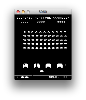
I’m kind of back in an emulator kick. I recently had dusted off my code that I had started for emulating the 8080 processor. I had originally wanted to implement a version of CP/M, but I remembered that the 1978 game Space Invaders was also based upon the 8080. It wasn’t hard to find a ROM file for it, and with a little bit of hacking, research and debugging, I had my own version of Space Invaders written in C and using SDL2, running on my Mac laptop.
Fun stuff. The sound is a little crude: most of the sound in the original game was generated by a series of discrete circuits which you can find on this page archived via the Wayback Machine. I briefly played around with simulating some of the sounds using LTSpice based upon these circuits (it appears to work fairly well), but I haven’t got that fully integrated into my simulator yet. For now, it just queues up some recorded sounds and plays them at the appropriate time. Everything is currently working except for the classic “thump… thump…” of their marching. I’ll get that working sometime soon.
Anyway, back to calculators. One thing on Ken’s page kind of made me think: he mentioned that the HP-35 had taken two years, twenty engineers, and a million dollars to develop. Mind you, the HP-35 was pretty revolutionary for its time. But I thought to myself “isn’t a calculator an easy hobby project now?”
After all, I had assembled a KIM-Uno, Oscar’s awesome little $10 board that emulates the KIM-1 microcomputer:
In fact, the KIM-Uno implements a floating point calculator as well. It’s brains are just an ordinary Arduino Pro Mini wired on the back. Arduino Pro Minis can be had for less than $3 from China. Could I make a fun little calculator using that as the basis?
My mind is obviously skipping around a lot at this point.
Of course, a bit more googling revealed that someone had done something very similar using the MSP430 chips from (appropriately enough, also manufactured by Texas Instruments). Check out the build thread here.. It’s pretty nifty, and uses a coin cell to drive it, as well as some very classic looking “bubble LED displays”, which you can get from Sparkfun. Pretty cool.
Anyway…
For fun, I thought it might be fun to write some routines to do binary coded decimal arithmetic. My last real experience with it was on the 6502 decades ago, and I had never done anything very sophisticated with it. I understood the basic ideas, but I needed some refresher, and was wondering what kind of bit twiddling hacks could be used to implement the basic operations. Luckily, I stumbled onto Douglas Jones’ page on implementing BCD arithmetic, which is just what the doctor ordered. He pointed out some cool tricks and wrinkles associated with various bits of padding and the like. I thought I’d code up a simple set of routines that stored 8 BCD digits in a standard 32 bit integer. His page didn’t include multiplication or division. Multiplication was simple enough to do (at least in this slightly crazy “repeated addition” way) but I’ll have to work a bit harder to make division work. I’m not sure I really know the proper way to handle overflow and the sign bits (my multiplication currently multiplies two 8 digit numbers, and only returns the low 8 digits of the result). But.. it seems to work.
And since I haven’t been posting stuff to my blog lately, this is an attempt to get back to it.
Without further ado, here is some code:
[sourcecode lang=”C”]
/*
* A simple implementation of the ideas/algorithms in
* http://homepage.cs.uiowa.edu/~jones/bcd/bcd.html
*
* Written with the idea of potentially doing a simple calculator that
* uses BCD arithmetic.
*/
bcd8
sub(bcd8 a, bcd8 b)
{
return add(a, tencomp(b)) ;
}
bcd8
mult(bcd8 a, bcd8 b)
{
bcd8 result = 0 ;
bcd8 tmp = a ;
bcd8 digit ;
int i, j ;
for (i=0; i<8; i++) {
digit = b & 0xF ;
b >>= 4 ;
for (j=0; j<digit; j++)
result = add(result, tmp) ;
tmp <<= 4 ;
}
return result ;
}
int
main(int argc, char *argv[])
{
bcd8 t = 0x00009134 ;
bcd8 u = 0x00005147 ;
bcd8 r ;
r = mult(t, u) ;
printf("%X * %X = %X\n", t, u, r) ;
}
[/sourcecode]
I’ll have to play around with this some more. It shouldn’t be hard to move code like this to run on the Arduino Pro Mini, and drive 3 bubble displays (yielding 11 digits plus a sign bit) of precision. And I may not use this 8 digits packed into 32 bit format: since I want 12 digits, maybe packing only 4 digits into a 32 bit word would work out better.
Anyway, it’s all kind of fun to think about the clanking clockwork that lived inside these primitive machines.
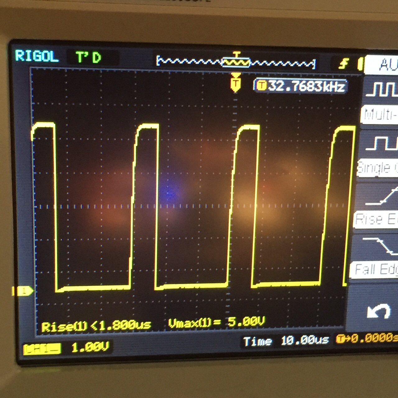
As I mentioned in a previous post, I was not enormously satisfied with the accuracy of the DS1307 clock module that I got from China. It was hard to argue with the less than three dollar price tag, but I was hoping that the accuracy might achieve 20ppm (less than two seconds of drift per day). My measured drift was over ten times that, about 25 seconds per day. Ungood.
It seems to have a dedicated 32KHz output, but it doesn’t run when solely on battery power.
The rise time of the 32kHz signal is pretty slow.
The duty cycle of the 32Khz signal is significantly below 50%.
The frequency as reported by my (not terribly accurate) oscilloscope’s built in frequency meter seems very close to the nominal 32768 Hz signal.
When I get time tonight, I’ll test it against my GPS and see what really works. My initial impression? Positive. If you care about even reasonable accuracy, paying a couple of bucks more for a clock module will probably be a good idea.
This morning I’m still drinking coffee and waking up, but I was pointed at “the ESP8266 wiki”, which appears to be this Wiki page. Bookmarked mostly so I can quickly find it again. But it has some good information. If I haven’t teased you enough with this experimentation, consider these features of the ESP8266:
It’s a wireless SoC
It has GPIO, I2C, ADC, SPI, PWM and some more
It’s running at 80MHz
64KBytes of instruction RAM
96KBytes of data RAM
64KBytes boot ROM
It has a Winbond W25Q40BVNIG SPI flash
It’s a RISC architecture
The core is a 106micro Diamond Standard core (LX3) made by Tensilica
The ESP8266 chip is made by Espressif
Modules bearing this chip are made by various manufacturers
And most importantly, you can get modules starting for as low as $3. You can get modules with the same chipset, more pins and USB for just $8.70 (plus shipping) (thanks MicroHex for suggesting it). And now, with the ability to program them from the Arduino environment? I’m definitely going to be experimenting with them.
Okay, after I did my quick video record yesterday re: the ESP8266, I continued to play with it a bit more. And, it must be said, I had a little bit of difficulty which I thought I would write up so that other people who are experiencing the same issues might be able to comment, and hopefully benefit as we get the problem resolved.
First of all, I observed a couple of different issues in just repeatedly playing with the board. Occasionally, the board would seemingly hang when a new URL request was received. It would print out an informational message that said that a new client had connected, but it wouldn’t actually print the message that it received. I had to recycle the power to reset it.
Secondly, when I had the LED connected, it would sometimes just fail to boot my program entirely. It would spew random crud into the serial monitor. Not good.
I suspect that both of these things might have to do with inadequate power supply. I am powering it entirely from a little 3.3v FTDI cable I had lying around (I believe it is this one, now retired.) If I read the datasheet properly, it appears that it can only power about 50ma of external circuitry. That’s simply not enough: I’m kind of shocked that it can boot at all. Peak current draw is probably somewhere around 300ma. Most every page on ESP8266 development says that I should use a high quality 3.3v power supply able to supply at least 500ma.
Next experiments will try to feature a better power supply. MOAR POWER.
Addendum: The module that I am using is the ESP-01. As you can see, it’s very simple, has only 8 pins, and is not breadboard friendly. Luckily for experimenters, there are other varieties of boards available based upon the same chipset. For instance, the ESP-04 has seven GPIO pins broken out, and can needs an external antenna. The ESP-201 is much more breadboard friendly, and includes both an on-board antenna, and UFL connector for an external antenna. There are lots of other types too, all very reasonably priced. If you haven’t bought the ESP-01 already, some of these other boards might be better to experiment with. But there are also people making various adapters for the ESP-01, such as the ESP8266 buddy, which sells for a paltry $2.50 and can adapt the ESP-01 to your breadboard. I think I’ll be getting a few of these.
In the telescope making world, we call the first time that a telescope is used to look at the sky “first light”. I’ve decided to call the first time I load some code onto a new development board “first electrons”.
A few weeks ago, when I did a video that illustrated some of the bucket of development boards that I had lying around, I decided that I should at least make a sincere effort to try to do something, anything, with each of them. Since then, I’ve discovered platformio which has enabled me to at least get some code running on the more obscure ARM based boards that I had lying around. Buoyed by that positive experience, I sought to see how I could get code running on some of the other boards. Tonight’s board was the ESP8266, a little cheap board (I paid $6 or so for mine, I’ve seen them on eBay for as little as $3) which are often used as serial-Wifi links, but which actually include a nifty little 32 bit SOC.
Luckily, the gods have smiled in the form of a three part article (Part 1Part 2Part 3) by Alasdair Allen for Make magazine. Previously, getting code to compile onto the ESP8266 required finding the right version of gcc and the download esptool, configuring it… Who has the time? What’s awesome is that now you can download a version of the Arduino environment that already has the necessary compiler and tools installed, and use the friendly, comfortable Arduino environment to compile and run code.
So, tonight, that’s what I did!
Conveniently, I had an 3.3V FTDI serial cable that I had purchased back when I was experimenting with 3.3V boards. That’s convenient, because otherwise I’d have to wire up a 3.3V voltage regulator, which isn’t hard, but at least takes one more step. Using the diagram in Part 2 of the article listed above, I setup some jumper wires to connect it all up. I then downloaded the necessary version of the Arduino environment (for my Linux laptop), installed it, loaded the WifiServer example application, modified it with my own network’s SSID and password, and tried compilation. It compiled fine, but when I tried to download the new code to the ESP8266, I got a communication error. I double checked all the connections against the diagram, no dice. Hmmph. There was one small bit of confusion that I always have when hooking up serial devices: the RX (receive) pin of one side needs to be connected to the TX (transmit) on the other, and vice versa. But when you try to document this, it can be confusing: if an end of your cable is labelled RX, does it mean that you should attach it to the RX? Or that the other end of the cable is RX, so you should connect it to TX?
I swapped RX and TX. And voila. The download works just fine.
To reboot and run the code, you need to remove one of the ground connections from the boad and cycle the power. I then fired up the serial monitor, changed the baud rate to 115200, and then watched it boot. It printed out that it was attempting to connect to my network, printed a series of periods, and eventually reported it’s IP address.
Nifty! I need to go dig up some current limiting resistors (maybe 220 ohms or so) so I can test it, but I verified that if I accessed http://192.168.1.116/gpio/0, it turns the gpio pin low, and http://192.168.1.116/gpio sends it high. Voila!
Well, with a few caveats. It seemed a little unreliable, and seemed to hang a couple of times. I’m not sure what the deal is. I’m suspicious about how much power my FTDI cable can actually supply, maybe that’s part of it. Or it could be software related. I’ll have to play with it more to be sure. But it’s pretty nifty. I’m sure I’ll be playing with it more. Good stuff.
Addendum: I dug up an LED and a 330 ohm current limiting resistor, and then recorded this trivial little demonstration.
As my recent video showed, I have a lot of development boards. I also have a fair number of little boards that are useful to plugin to these development boards to accomplish various tasks. Yesterday, I received a little OLED board that I thought I’d try hooking up and let you know about my experience.
There are lots of boards out there that apparently use the same screen: a 0.96″ OLED display with a resolution of 128×64. I ordered this one from Amazon for only $9 with free shipping. The description is a little bit misleading: you can find versions of these kinds of boards that have 7 or 8 pins and use the SPI bus. This one has (and requires) only four pins, and uses the I2C bus. I’m no expert on the technical differences, but my general impression is that SPI is full duplex and can run at higher speed and at longer range, but requires individual chip select lines for each device, where the I2C bus uses chip addressing, so no additional wires need to be hooked up to select the proper target device. (If any of my genius readers care to correct me on that, feel free to leave a comment).
Here’s a picture of the module I got, as I tweeted it yesterday:
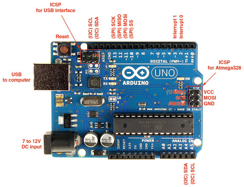
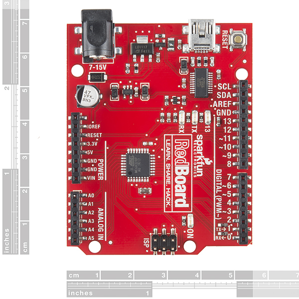
It’s safe to run on either 5v or 3.3v, without any level converters or other nonsense. I hooked it up to one of my Sparkfun RedBoard Arduino clones. I plugged it into a bread board, and then wired up the four connections. VCC goes to the 5V pin on the Redboard, GND goes to one of the Arduino grounds. The remaining two lines need to be hooked up to the SCL (serial clock) and SDA (serial data) lines on the Arduino. This caused me a minor bit of confusion: on an Arduino R3, those two pins are on A4 and A5.
On the RedBoard, these pins are split out separately onto separate pins near the AREF pin.
I connected them to the SCL/SDA connectors on the RedBoard. I suspect that on the Uno R3, A4/A5 are the connectors you’ll need. Other variants of the Arduino might need different pins.
And, of course you’ll need some software. It’s tempting to go to Adafruit for all things Arduino, but in this case it can be a bit of a mistake I think, or at least it might require a bit of tinkering. Adafruit sells their own OLED boards, but they are a bit more costly and are wired a bit differently, and I thought that might make their software a little trickier to configure.
Instead, I found the U8G graphics library. It’s fairly nice because it supports a wide variety of boards, and is self contained. If you download the Arduino code and unzip it into the Arduino library directory and restart the Arduino environment, you’ll see some examples installed. But if you load one and try to compile it, you’ll encounter an error: the examples aren’t configured for the particular board you need. To do that, you need to uncomment the right definition for the graphics device.
For this specific device, you want to delete the two slashes at the start of this line. This selects the I2C bus, and tells it to use the SSD1306 chip that is on the board. This one worked for me.
So, I downloaded the “Graphics Test” example, made that modification, compiled it and downloaded it to the RedBoard. Voila
A pretty neat little display. I must say that it’s a bit too tiny for my old-guy eyes to read when the print is small (damn you presbyopia!) but It’s very sharp and clear. If you have need of such a device, this one seems inexpensive and easy to use. Check it out.
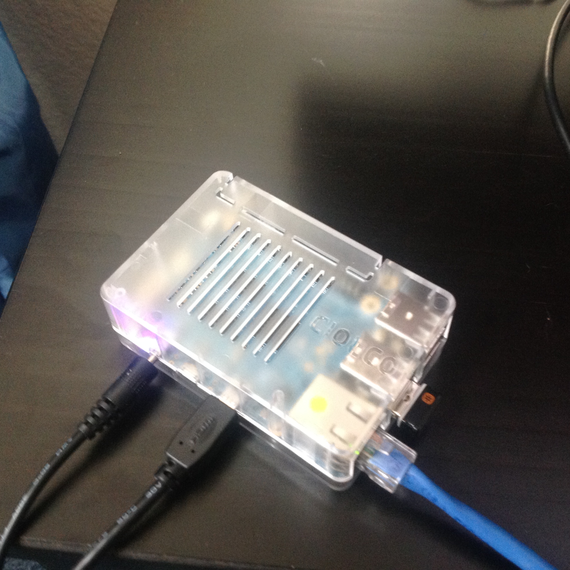
One of my recent posts highlighted the big pile of development boards that I have lying around. This week, I actually added to that pile in a couple of ways: I found a pair of Beagle Bone Blacks that I had misplaced, a couple of Propeller boards, and most significantly, I ordered an ODROID-C1 from ameriDroid. Stupidly, I didn’t read their website carefully enough, so I ended up making TWO orders from ameriDroid, the second to get the somewhat odd power supply needed (5V, 2A, with 2.5mm barrel) and to which I added the clear case you see, and also a micro HDMI cable (I know I have one some where, but I couldn’t find it). The prices for the additional goodies swell the price a bit, but are quite reasonably priced: $4.95 for the case, $5.95 for the HDMI cable, and $6.95 for the power adapter. Consider carefully before ordering and you’ll save a round of shipping.
ameriDroid did an excellent job of shipping: I had BOTH orders delivered just two days after ordering. They even included this nice hand written thank you, which makes more sense when you realize I had this delivered to my work address.
In the following discussion, when I mention the Raspberry Pi, I am speaking of the older variation model B and the B+. I do not yet have a Raspberry Pi 2, which upgrades to a 900Mhz quad core with 1GB of DRAM.
Given that I have four Raspberry Pis and three Beagle Bone Blacks of various generations, what compelled me to look at the ODROID-C1? You can read the specifications yourself, but here are the things that were most intriguing to me:
Quad core 1.5Ghz ARM processor. Compared to the 700Mhz single core ARM in the Raspberry Pi and the 1Ghz CPU in the Beagle Bone Black, one might expect that this little board could handle a lot more stuff.
1GB of Dram, double most of my other boards. Nice!
Supports some little eMMC4.5 flash boards, which are supposed to be faster than existing microSD cards (more on this below).
4 USB ports + 1 USB OTG port. Lots of expansion capabilities.
Includes an infrared receiver built onto the board. Might be cool for remote/home theater applications.
Supports both Ubuntu and Android. I’m mostly a Linux guy, but the possibility of using recent Android builds is interesting too.
Okay, so on to my experience…
I didn’t order any of the memory cards from ameriDroid with the operating systems pre installed. Why? I’m kind of a cheapskate, and I have a couple of spare 16GB microSD cards lying around. I started with a class 10 Lexar card. From my Ubuntu laptop, I downloaded their version of Ubuntu (1.1GB compressed, around 4gb uncompressed) and did the usual dance using the Linux “dd” program to copy it to the flash card. I also got an Edimax Wifi dongle from one of my other Raspberry Pis, and the wireless keyboard dongle. Plugged all this stuff together, plugged the microHDMI cable into my old Samsung TV, and powered it on. And…
Nothing. Screen went black on the TV, and the two LEDs on the board (red and blue) were steady and mixing to purple color. Hmmph.
A little googling revealed that if Linux had booted, it would be flashing the blue led as a heart beat indication. I decided to go ahead and try reburning Linux onto my other flash card (which it turns out is a slower class 6 Lexar card). After all, earlier this week I discovered that one of my unbootable Raspberry Pis was in fact an issue with SD card compatibility.
And, of course… that worked! Up until a point. My TV is rather old, and just supports 720P. When it booted, I ended up with my tv saying “Video Mode Not Supported”. Grrr. It turns out that you can change that by modifying the boot.ini file on the card (easy to edit if you have another Linux box, mount the card, edit the file to select 720p, save, eject, and reboot).
And that worked. Again, up until a point. On my TV, overscan is a bit of an issue: a significant amount of the screen (including all of the all-important task bar) was actually off screen on my TV. Grr… I drug out a monitor which didn’t have the overscan issues. And rebooted.
Into a nice X-windows desktop. It wasn’t the Unity layout that I was familiar with from my desktop, it’s more old school. On the desktop is a README and an icon labelled “ODROID Utility”. You click on it, and it allows you to do some features similar to those performed by the “raspi-config” program on the Raspberry Pi: most notably, to upgrade the kernel/firmware and expand the root partition to take full advantage of the entire microSD card. If you select the “upgrade kernel”, it actually doesn’t do that, it tells you that you can use the normal “sudo apt-get update; sudo apt-get upgrade; sudo apt-get dist-upgrade” commands to update. But I did try to expand the drive, rebooted, setup the wireless network using the desktop utility, and then started the apt-get stuff…
But something along here went wrong. Even after rebooting, it didn’t appear that the card was expanded, but I didn’t notice until the upgrade was underway. There were a couple of other oddities: ssh didn’t appear to be working right, I couldn’t login remotely. And the Edimax Wifi was really, really slow: just a few kb per second. That upgrade was going to take forever. And while that was happening, I noticed the odd “unexpanded” root partition, which appeared to be out of space. Argh!
So, I redid the entire process again: reflashed the OS, and redid everything again. I also decided to ditch the Edimax connector, and instead plugged the board into my wireless router via Ethernet.
And somehow, things worked better. I’m not sure what I did wrong, but when I tried to expand the root FS, it told me to check to make sure that the root device was on /dev/mmcblk0p2. I exited first, and ran df to check, and it told me that it couldn’t access the mount table. “What the heck?” I decided to reboot again, and it showed up properly, not sure why. In any case, I expanded the root fs and rebooted. This time, I saw 11GB free, and decided to proceed with the apt-get upgrades.
Now that I was hooked up via Ethernet, things seemed to work much better. It still took a couple of hours to update all this stuff, but it did, and now it’s running pretty well.
If you “cat /proc/cpuinfo”, you get:
odroid@r2d2:~$ cat /proc/cpuinfo
Processor       : ARMv7 Processor rev 1 (v7l)
processor       : 0
BogoMIPS        : 3.27

processor       : 1
BogoMIPS        : 3.27

processor       : 2
BogoMIPS        : 3.27

processor       : 3
BogoMIPS        : 3.27

Features        : swp half thumb fastmult vfp edsp neon vfpv3 tls vfpv4
CPU implementer : 0x41
CPU architecture: 7
CPU variant     : 0x0
CPU part        : 0xc05
CPU revision    : 1

Hardware        : ODROIDC
Revision        : 000a
Serial          : 1b00000000000000
Nice! Quad core. It still doesn’t seem super fast, no doubt because of the slow flash cards. You can ssh in using the login odroid password odroid. You can run sudo or su with the same password.
It was a bit of a hassle, but it appears to work.
Overall, the biggest problem I have with the ODROID thusfar is the Ubuntu distribution is just too bloated. It loads a whole bunch of software that might be reasonable on a desktop, but seems out of place (at least by default) on a small system. The Raspbian distribution of Debian actually walks this line pretty carefully: it feels fleshed out, but by default doesn’t include absolutely everything you might want, because after all, you might not want all this stuff, and resources on these small boards are fairly scarce. I don’t think I need the jdk, cups, kido (I had to look it up too), samba, chrome and firefox (runnable, but not all that pleasant in low memory systems) and god knows what else. This also means that getting your system up to date is slow too, because there is just so much software to update. Bleh.
It’s also pretty clear that the ODROID distribution is just less polished. The Raspberry Pi might annoy me with its (understandable) insistence on setting your keyboard up for UK English, but it’s easy enough to change, and raspi-config handles most of it. Ubuntu on the ODROID seems curiously to come with the default time zone set to Australia/Adelaide, and I had to google for the dpkg-reconfigure magic to fix it. Your expectations and experiences might be different.
One of my twitter followers asked whether I had bought the eMMC card with Ubuntu pre-installed. I did not, and the reason is simple: I’m a cheapshake. I think I paid ~$10 for my last 16gb microSD card, whereas the 16gb eMMC cards sold by ameriDroid cost $40 (more than the entire rest of the computer). Whether they are speedy or not, it didn’t seem like economy to me.
A few last thoughts after my first day as an ODROID-C1:
If you are a relative beginner to Linux, I don’t think I’d allow myself to be seduced by the ODROID’s higher speed. Get yourself a Raspberry Pi 2: definitely setup better for newbies, and has a much larger community to draw from. I found the learning curve for the ODROID to be a bit steeper than I think newbs could handle.
The ODROID-C1 could use a more disciplined Ubuntu distribution. The existing one includes everything and then some. A smaller but more reasoned distribution would be nicer.
I have not figured out what the deal is with the microSD card that wouldn’t boot. I am told that Samsung cards are in general better, but more investigation is clearly needed. I’ve no doubt that the class 6 card I’m using is slow, but the class 10 card I tried didn’t work. More experimentation is clearly (but sadly) still needed.
I should experiment with wireless again. I’ve had good luck with the Edimax dongles on the Pi, not sure what the issue might be.
Buy the AC adapter when you order one. And the HDMI cable if you don’t have one.
A lot of the documentation is obviously kind of bad translations. Even their videos can be a little bit mumbly and hard to understand:
Are any of my other readers using the ODROID-C1? I’d love to hear your comments and experiences.