Category Archives: electronics

The art of capacitive touch sensing

I didn’t get a lot of electronics hacking done, but I found myself again playing with capacitive sensing. I found this interesting article on the EE Times website:

The art of capacitive touch sensing

It also pointed me at the following pretty cool Youtube! vid by the folks at Nerdkits:


My experimentation thus far has been mostly confined to using the CapSense library for the Arduino. This library is pretty simple to use, but it has a number of quirks that make it somewhat cumbersome for the uses that I had for it. I’m currently working on a “better” (for my purposes) version. Stay tuned.

The Sparkfun Serial LCD

I was driving around various Silicon Valley electronics and surplus stores (like HSC and Anchor Electronics) and decided to stop in at Microcenter. I remembered that they supposedly were beginning to stock items from Sparkfun and the Maker Shed. And, indeed they do! I found a Serial LCD module from Sparkfun that I thought might be fun to have, so I got one:


A couple of quick caveats though:

  • The module has absolutely no documentation in the box. A quick bit of searching revealed the datasheet for the device, and that was helpful (although not the clearest that I’ve seen). If you are familiar with HD44780 devices, you’ll have no problems.
  • The pigtail they ship with it connects to the JST connector, and uses stranded wire. Not the best thing to plug into breadboards and the like. I soldered some female headers onto the unpopulated connector, and that worked out better.
  • It doesn’t appear that you can load custom characters over the serial interface like you can with the traditional interface. Bummer.

Still, it was dead easy. If you want a simple module to do some simple display tasks with only three wires, it works just fine.

Using a 1N4148 diode as temperature sensor…

I had an application where I wanted to detect temperature. No big deal, lots of good temperature sensors exist. But of course, I don’t have any of those. Rather than order something from sparkfun, I thought I’d just try to see what I could do with the stuff I had on hand. What I had on hand was about 100 1N4148 diodes that I got for about a penny a piece.

The idea is that the forward voltage of diodes is temperature dependent. For every degree Celcius the diode increases, the forward voltage should drop by 2mV. So, I decided to test this idea. I configured the analog input pin 0 on my Arduino to be an input, and then activated its internal pullup resistor. I then wrote a program which averaged a bunch (1000) of readings in an attempt to get a stable, relatively noise free signal.
I logged the values beginning at room temperature, then held the diode between my fingers, and then released it a couple of times. Here’s a graph of the resulting data values:

You can see that when I grab the diode, the forward voltage drops rather quickly, but when I release, the signal returns to the original value, somewhat more slowly. Room temperature in my house is around 70 degrees (21 degrees C) and body temperature is 98.6 is about 37 degrees C. The difference would then be about 16 degrees C, and we might expect a difference of 32 mV, but I experienced a difference of only about 16mV. At least part of this can be attributed to the fact that your finger temperature isn’t actually that close to 98.6.

This simple experiment demonstrates a couple of problems: the values returned by analogRead() are noisy, and quantization error is significant. The analogRead call returns a 10 bit number, which means that each bit is about 4 mV, or about 2 degrees C. We could use an operational amplifier to multiply the voltage to make it easier to read, which might help. Consider that an experiment for the future.

A cool little computer: FIGnition

I keep looking for cool projects where people build small computer and microcontrollers, more or less from scratch. Today, I ran across FIGnition:

FIGnition is a £20 educational DIY computer which works like an 8-bit home Micro: outputting to composite video and ready to be interactively programmed from the moment you switch it on. It has  8Kb of RAM; 384Kb of storage; an 8-key keypad and runs a variant of FIG-Forth. It uses USB for power; firmware upgrades and program downloads.
via fignition – Libby8dev

Very cool little Forth-based computer, using at ATmega168, a small 8K serial RAM and an SPI flash memory chip. You can either buy a PCB board, or you can assemble it on strip board. Lots of good ideas!

A Low Power 477Thz beacon

I mentioned that Roger, G3XBM was shifting from the very low frequencies to much higher frequencies. His interest has already uncovered some links that I hadn’t seen before. One very cool thing was his discovery of a local 477Thz beacon (that’s red light) that is aimed roughly in his direction at a distance of around 30km. The beacon is the work of GB3CAM, and uses ten 10mm red LEDs, running with about 400mw DC power input. What a cool idea! The entire circuit consists of a PIC processor and an XR2206 monolithic function generator.

Check it out!

It appears that the UKNanowaves group on Yahoo! is a pretty lively group. I’ll be watching this closely.

Arduino PPT Solar Charger

A conversation I had recently got me on the topic of solar energy, and introduced me to something I hadn’t heard of before: maximum power point tracking. The basic idea is solar cells exhibit a complex non-linear relationship between illumination, temperature and resistance. This is usually represented by an curve that (for a given temperature and level of illumination) shows the relationship between current and voltage. Let’s swipe the diagram from wikipedia:

To maximize the transferred power, we want to maximize the power of the solar cell. This means operating the DC/DC converter at the particular point along the I-V curve where the area under the rectangle is maximized. Tim Nolan has designed a pretty cool circuit that when combined with an Arduino can do precisely that:

timnolan – Arduino PPT Solar Charger.

The details of the design are a bit beyond me at the moment (I’ve studied it for about 20 minutes) but the basic idea is to sample the voltage (via a voltage divider) and the current (derived from the voltage drop across a very small current sense resistor, amplified by an op amp), and then use the PWM capabilities of the Arduino to serve as a switching dc/dc converter. Very neat little circuit. I’ll study it more in the future.

ANGST: the Arduino n’ Gameduino Satellite Tracker

I’ve stopped hacking on my Arduino/Gameduino satellite tracker for now. Here’s the final video demonstrating it running:


I’m currently working on the final schematic which will be posted on this permanent page. The code will be available github.com, for right now, it includes the library that I wrote that does the satellite prediction. I’ll be updating the code sometime later this week.

If you take it and use it, let me know: it will motivate me to do more with the code.

JeeNode v6 Kit from Modern Device

I’ve been playing a great deal with Arduinos lately, and have acquired a couple of Xbees to experiment with wireless. But Xbees, cool as they are, are kind of expensive for many tasks where a much simple RF link could suffice. Today, I ran across the JeeNode, which is available as a kit from Modern Device for just $22.50, and that includes a 915Mhz RF link. You’ll need an FTDI cable to program it, just like any other low cost Arduino. Pretty neat!

JeeNode v6 Kit | Modern Device.

KD1JV on boost and buck converters implemented with an ATtiny13V

Legendary QRP hacker Steve “Melt Solder” Weber has some awesome stuff on his website, particularly if you are interested in homebrew ham radio gear.   (Indeed, it appears he’s about ready to offer his legendary ATS-4 5 band rig kits again, experienced kit builders might want to check it out.)   But what drove me to his website this morning is quite clear exposition of buck and boost voltage converters in PDF form. Remember my ATtiny13 powered Halloween pumpkin? It was inefficient: about half of the power consumed in the circuit was simply lost as heat in the current limiting resistor. Had I read Steve’s exposition a month out from Halloween, I might have tried to do better.

Here’s the relevent circuit cribbed from his PDF:

Pretty simple! A couple of things to note: the NDT2955 is a logic level P type MOSFET, which turns fully on with a gate threshold of just 4V. Readers may remember that my own experiments with the IRF510 didn’t succeed in some small part because the IRF requires 10V to switch entirely on. Secondly, the ATtiny13 is powered directly from a 6V supply, through two diodes. These are there simply to drop the voltage to the 5.5V level which is the maximum safe amount. The ATtiny13V is very forgiving on voltages, and can operate all the way down to 1.8V, long after the batteries will have given up the vast majority of their power.

I’ll try to work through the equations and design a similar driver for my 1W Cree LEDs. To build it, i’ll need to come up with an appropriate MOSFET. Stay tuned.

Some simple circuits with solar cells…

My tinkering with my ATtiny13 based pumpkin circuit had me thinking that perhaps I should try to make something similar, but solar powered. Luckily, Windell had already anticipated my needs, and had put up a nice simple page with some circuits to experiment with. If you want a simple solar battery charger, or a simple solar powered microcontroller, try checking this out:

Simple Solar Circuits – Evil Mad Scientist Laboratories.

STM32L-Discovery: What should I build with it?

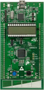
I got one of these boards the other day for free:

STM32L-DISCOVERY – STMicroelectronics.

Even if you didn’t get one for free, they seem to be pretty cheap: Nu Horizons has ’em for around $15, Mouser has them for $11.67, which makes them pretty much cheaper than every Arduino you can order. But what do you get for your dollars?

  • 32 bit processor with 128K flash, 16KB of RAM, 4KB EEPROM
  • DIP28 LCD Display
  • Linear touch sensor
  • Two user programmable LEDS
  • Can use either 5v or 3.3v supply, including power supplied by USB

Examining the information about the processor, the STM32L152RBT6, it appears to be based on the ARM Cortex M3, with a maximum clock rate of 32Mhz. The processor is optimized for very low power consumption, it only consumes 9 microamps of current at 32kHz in low power mode, and 230 microamps?Mhz in “dynamic run mode”. That sounds pretty cool! It’s data sheet says that it has 10 timers, up to 8 communication interfaces (including a full speed USB 2.0 interface) and a 12 bit ADC. From the data sheet:

A 12-bit analog-to-digital converters is embedded into STM32L15xxx devices with up to 24 external channels, performing conversions in single-shot or scan mode. In scan mode, automatic conversion is performed on a selected group of analog inputs. The ADC can be served by the DMA controller. An analog watchdog feature allows very precise monitoring of the converted voltage of one, some or all selected channels. An interrupt is generated when the converted voltage is outside the programmed thresholds.
The events generated by the general-purpose timers (TIMx) can be internally connected to the ADC start trigger and injection trigger, to allow the application to synchronize A/D conversions and timers.
The ADC includes a specific low power mode. The converter is able to operate at maximum speed even if the CPU is operating at a very low frequency and has an auto-shutdown function. The ADC’s runtime and analog front-end current consumption are thus minimized whatever the MCU operating mode.

All that sounds pretty cool!

Anybody have any good ideas of something I can do with it? Go ahead and leave a comment, or hit me via Twitter (@brainwagon) with your suggestions.

Nyle Steiner finds and demonstrates a memristor

Nyle Steiner, of the Spark Bang Buzz blog has been at it again, demonstrating cool electrical/electronic devices that are homebrewed. This time he constructed his own memristor.

If you aren’t up on electronics, you might not have heard of memristors before. While Leon Chua proposed that such a circuit element was possible, they weren’t actually created in a lab until 2008. But what is a memristor? It’s a circuit element whose resistance depends on the sum of the charge flowing through it. In other words, if you pass a voltage through a memristor in one direction, it’s resistance increases. If you pass a voltage through the other way, it decreases. But if you stop the voltage entirely, the memristor “remembers” the previous value it had, and will keep the same resistance it had when the charge was cut.

Amazingly, Nyle Steiner observed this memory effect in some brass shell casings which had been oxidized in a sulfur environment (I’m no chemist, so I won’t try to explain that part) over 10 years ago. He made this short video demonstrating such a memristor using both a curve tracer (which may take a few minutes of though to understand exactly what is going on) but also through a very basic circuit demonstrating how the memristor can “remember” a single bit and turn an LED on and off. If you didn’t know that memristor’s existed, you’d probably be forced to try to explain the behavior of the circuit in terms of capacitance: but unlike capacitance, the memristor doesn’t need to be refreshed to maintain its state. You’d find it rather puzzling, to be sure.

Awesome stuff.


BeagleBone, a new ARM-powered embedded platform

I really like the Arduino, but even I must admit that performance-wise, it can be a little, well, disappointing. A 16Mhz 8 bit processor can do a lot, but there is also a lot of applications where having something a bit beefier makes a lot of sense. Something with support for a richer peripheral set, like USB, Ethernet, and video.

Thus, it is with some interest that I learned of the Beagle Bone:


The Beagle Bone

I haven’t got one, but there are a couple of features which I think make it attractive:

  • The price is $89. Yes, it’s more than an Arduino, but it’s not a lot more than an Arduino Mega, and it’s not any more than an Arduino Mega and an Ethernet shield.
  • Web based development environment. This is kind of a mixed bag, but one of the advantages of the Arduino environment is that it’s a one stop shopping trip to get setup: there isn’t a need to install a lot of different tools to get going. For hobbyists, letting people get right to work is a big plus.
  • Enough power to run OpenCV and the like. The Arduino is simply too underpowered to even think of doing anything like that, so the Bone represents a big increase in functionality.
    It runs Linux. Yes, it’s kind of fun to run on relatively naked hardware, but sometimes it’s more expedient to have some support for multitasking.

A couple of nits to pick though: I thought it should have included some kind of video interface on the base board. The $89 price point begins to look less and less attractive if you have to get a $20-$30 daughter board to provide the video interface.

I also think that it’s just a bit more expensive than I would like. If you compare it to the feature set of another microcontroller in the works, the Raspberry Pi, with a price of $35 dollars (for the Model B) with ethernet and video, but without the same level of expandability, the Raspberry Pi might be a good choice for education and hobbyist level hacking at a lower price (indeed, a price equal to an Arduino Uno).

To be fair, you can buy an Arduino Uno today, whereas the Beagle Bone and the Raspberry Pi are both still in the works.

It’s a great time for the hobby computer hacker though.

A Constant Current LED Driver…

While tinkering with my ATtiny13 Pumpkin Project, I ended up using a fairly inefficient circuit: the same amount of power is dissipated in the current limiting resistor as in the LED itself, which mean that at best, the efficiency would turn out to be around 50%. In reality, some power is consumed by the switching transistor, so it’s more like 35% or so, and when driven at the maximum power level of the resistor, the 2N2222 got uncomfortably warm.

In staring at some “constant current” sources, I began to understand what was going on. I put this circuit into LTSpice to help me understand:
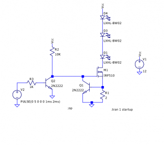
The key to understanding how this circuit works is what happens at the base of Q1. It be around 0.65v higher than ground. That means the current through R1 is essentially constant (that’s good, from my LED’s view). 0.65 volts divided by two ohms means about 330 ma (which is pretty close to 100% of the limit of the LED current). The forward voltage drop for these LEDs is around 3.2V, so we are right around 1 watt of power per LED. The MOSFET is forced to absorb some current, because there is still some remaining voltage drop, if you do the math, that works out to about 1.75 volts, which multiplied by the current turns out to be 575mw. The overall efficiency works out to be around 75% or so. Not too bad. The 2N2222 transistors consume very little current.

If we actually had an 11v supply instead of a 12v supply, the efficiency would be a bit better: the current through the LEDs would remain unchanged, but the power consumption would drop by more than half. At 10v, the voltage supplying the gate of the MOSFET begins to swing to Vcc, and the MOSFET power consumption drops to around 40mw or so, but at 10V, the voltage drop through the LEDs is too much to maintain the 0.65V needed at the base of Q1, and the current drops. We can compensate a bit by changing R1 to a 1Ohm resistor, and when we do, we see that the circuit becomes very efficient (about 1W per LED, with overall circuit consuming about 3.2W).

I’ll try to get a circuit like this on a breadboard for some practical experimentation soon…