Category Archives: Embedded

Musing about a 2 dimensional delta robot…

First of all, if anyone is still swinging by this blog, yes, I’m still alive. While I haven’t exactly been prolific in my leisure activities, they haven’t stopped entirely. I worked on some simple embedded development for the hackaday.io 1K code challenge, which you can see on my hackaday.io page, and which hopefully I’ll write up here. I’ve got some additional projects in mind, so perhaps with a little extra effort on my part I’ll be getting back to more regular entries.

One of the things that has been kicking around in my head is to “make something that moves.” In particular, I’ve long been interested in gadgets like plotters, 3d printers, laser cutters and CNC machines. A few months ago on a whim, I ordered a CNC shield and Arduino so that I could begin to think about maybe creating a project which drives some steppers around to trace some pattern. I doubt that I possess the skills or know-how to do a good job of making a real CNC machine, but I kind of liked the idea of making a plotter. I started to work on the basic mechanical design of a simple 2D gantry. But frankly, I began to balk at the idea. You need two different sets of parallel ways, which seemed large and cumbersome, and each axis is different.

At the Maker Faire I had observed some simpler setups which generally go under the name of “Drawbots”. You can see an excellent write-up here on the “Death To Sharpie” page. I liked the idea a lot: it uses two steppers and the setups for each are symmetric. Each one winds and unwinds a chain, and the pen is suspended at the intersection of the two chains. In this incarnation, the pen doesn’t even have a separate control: it is simply drug around the poster board, leaving a trail wherever it goes. Pretty cool! I must admit though, I thought his software setup (laptop + Raspberry Pi + Arduino?) was a little complicated, and I’d probably enjoy working on the control software anyway.

But I was discussing this with my constant lunchtime companion Tom, discussing catenary curves and the like, and he basically said “why don’t you just use solid arms, making a 2D analog of the 3D delta robots you see in 3D printers?”

An awesome idea! One of the cool things about constructing a delta robot is that it consists of three essentially identical pillars. Yes, the three pillars all move slightly differently, but that is really a software issue, not a hardware one. A few moments of thought and I realized that you could make a pretty spiffy 2D version, and the math would actually be pretty easy.

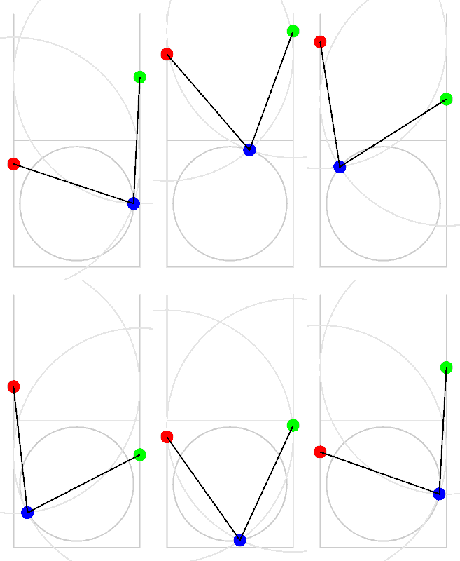
So, in between tasks, I worked out the necessary quadratic equations, and created this gif that will demonstrate how the motion works.

The work space is the unit-size gray square at the bottom. It is bracketed by two rails, each of length two. Each has a carriage which runs along its side, and pins one end of a fixed arm (again, of unit length) which are held together in the center by a pin, which is where the pen will be. As you drive the red and green carriages back and forth, the intersection moves back and forth. It isn’t hard to see that the pen can reach any location in the unit square at the bottom.

It isn’t quite as compact as the typical drawbot, but I can’t help but think there are some serious mechanical advantages to setting up a bot this way. It should not be very hard to create an interpreter that could run on the Arduino that would take a small subset of G code and some basic scaling and rate information, and drive a pair of steppers to create this kind of a robot. I’ve never written code exactly like this before. It should be fun.

Stay tuned.

Ordered some ESP8266 boards in an Arduino form factor…

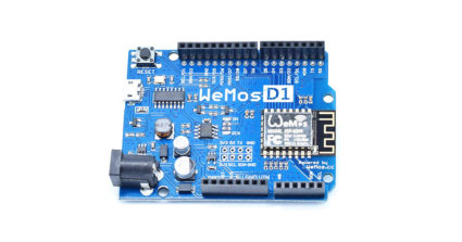
r2_1The ESP8266 is an amazing little processor: cheap and capable and (most interestingly) WiFi enabled. I have some of the older “nodemcu” boards that I got for about $7 each, but there are newer alternatives that include up to 4M of flash memory, and a variety of interesting form factors.

I noticed that WeMos was producing these boards which nominally have the Arduino Uno form factor. With a 15% discount coupon from banggood.com, I got three of them on order for under $16. I’ll let you know how they work out. I’m normally not a fan of the classic Arduino shape, but I do have a number of 3d printed cases and bumpers that can be used, which makes them relatively easy to mount and wire up.

If you want to program the ESP8266, you might try using platformio, which makes it easy to use both the native SDK as well as a simpler Arduino based framework. It also supports a number of other embedded architectures, including the Arduino, but allows you to use your own editor and the like to build and organize your code. Worth looking at.

Two bits of hardware on order…

Yes, my fascination with cheap computing devices continues. I’ve got two bits on order at the moment.

First is the Pine A64 from Kickstarter. This one won’t be showing up for a while, but seems to be a pretty nice piece of kit. You can think of it as a competitor for the Raspberry Pi, but it’s got a few additions that seem pretty interesting. You can order them with up to 2G of RAM, it can drive a 4K display, it has a real time clock, and it’s actually cheaper than the Pi.


Second is the LinkIt Smart 7688 Duo from Seeedstudio. It should ship to me fairly quickly, and I’m pretty excited by it. It runs Linux OpenWRT, which I have had some experience with on other router hardware. It’s tiny and limited, but still powerful. I view it as basically competition for the WRTnode, which has similar specs and also runs OpenWRT, but this one nicely includes a microSD card slot. I will try to get it up and running and maybe do a comparison between the two when I get it.

Stay tuned.

The ESP8266…

I’ve been quiet lately, but mostly because what tinkering I’ve been doing has been relatively limited in scope. But one thing I have begun to play with a lot are various tiny development boards based upon the Espressif ESP8266 WiFi chip. I’ve mentioned them a bit before, but I’ve made some progress since then (and the platform has as well) so I thought I would give you an update.

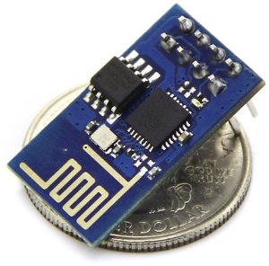
51oc+lvXC3L._SX300_First of all, the hardware. There are lots of different development boards which use this chipset. The smallest and least expensive is the ESP-01, which probably costs around $3.50 if you look around, maybe even cheaper via eBay. You’ll pay about $7 or so from Amazon or the other major dealers, but companies like ElectroDragon have them for half that. The ESP-01 is really small, but not very breadboard friendly, since it has its 8 pins in a 2×4 array. They also have a fairly limited number of GPIO pins: notably, two (and GPIO 0 needs to be able to be pulled low to start the flash bootloader).

You can get a plethora of other modules (popular ones are the ESP-12 surface mount modules) that bring more pins to the output, but I wanted something with the ability to be put in a breadboard for experimentation, so I stared at three different modules:

  • The NodeMCU which I purchased from Electrodragon. This was the first version of this board, which has a couple of quirks: it’s wide, almost takes up the entire width of the breadboards that I have, which is kind of annoying. It also has a yellow soldermask with white lettering, which is pretty difficult to read, even with bright light and magnification. And, it uses an offbrand serial/USB chip which is supported under Linux, but might require driver downloads if you have Windows or Mac OS X. I’m told that their new version fixes that: it’s narrower because it is based upon an ESP-12E module, it uses the slightly more common CP2102 chip for serial/USB and as a bonus, it doesn’t require you to hold down the rest key to reprogram. I don’t have one of those yet, but it seems like a pretty nice little module.
  • The Adafruit Huzzah board is similar to the ElectroDragon, but has a couple of nice changes. First of all, it’s a product of Adafruit, and I like to support companies that actively support user communities. It’s similarly small, but has much nicer labels that are reasonably easy to read. Unlike the ElectroDragon board, it has just a raw TTL serial connection (six pins on the end) so you’ll need a USB/Serial cable to talk to it and program it. Luckily, this design has included circuitry to change the levels of the TX/RX lines to be compatible with 5V programming cables, which are a bit more common. Note: there is no level shifting on the other GPIO pins. The board comes shipped with a couple of rows of header pins you have to snap off and solder in place yourself. I would have liked it had they included a 6 pin right angle set too: when you solder in the programming pins, they are pretty close to the reset button which you need to hit fairly often, making them right angle would have helped. It comes programmed with the NodeMCU firmware, which is based upon the Lua programming language, which is a compact programming language that has gained some popularity in the game world. More on that later…
  • The Sparkfun “Thing” board is a similar board which is a bit more expensive ($16) but has some additions that make it attractive. Most notably, it has an on-board LiPo battery charger and power supply, which means that if you wanted to do something battery powered, this might be a good way to go. Like the Huzzah board, it needs an FTDI cable, but it does NOT have levelshifting, you should use the 3.3V programming cables. I don’t have one of these yet, but I probably will soon. It should also be noted that Sparkfun also has a $15 WiFi Shield that you can attach to the Arduino, which is basically has the same brains, but put in a formfactor that can easily attach to an Arduino. Very nice.

Out of the box, each of these boards except the Adafruit Huzzah supports the “AT command” firmware. If you are as old as me and remember the days of the Hayes Modem, you might remember issuing AT commands to the modem to get it to dial a remote BBS. This firmware works kind of the same way: there are a bunch of commands which begin with AT that allow you to connect to local WiFi networks, establish network connections, and send and receive data. If you have a project which uses the Arduino (or almost any other small micro like the Teensy) that you want to connect to the Internet via WiFi, using one of these modules with the AT command firmware might be a reasonable way to go. You merely attach the serial port on the ESP8266 board to your Arduino, and then you can send commands to it and receive data back. Very cute.

But the system itself is more powerful. The processor on the board is surprisingly capable: it’s a 32 bit processor, running at 80Mhz, with 64 K of instruction RAM, 96K of data RAM, and 64K of boot ROM. It has 9 GPIO pins, and can do I2C, SPI, PWM, and even has a slightly odd ADC channel (max voltage 1.8v). And, what’s pretty neat is that the manufacturer has done quite a bit to encourage people to program them. They release a set of SDK libraries which are reasonably complete, and lots of people have starting writing their own programs in C/C++. When used this way, the boards may not even need a separate microcontroller like the Arduino: it can do all the work itself.

I’m not going to explain all the details here, but you’ll need a compiler and a tool for downloading code to the ESP8266. There are several ways that you can do that:

  • I like to use PlatformIO, which supports ESP8266. If you are interested in doing code for embedded development boards, check out platformio. I’ve mentioned it before, and I’m super glad that the ESP8266 is supported. Basically, it’s a simple command line shell that enables you to ignore a lot of the download/compile/configuration of the tools you’ll need. You simply tell it to build a project for the ESP-01 with the command “platformio init –board=esp-01” and it makes sure that you have all the right libraries/compilers/utilities. It also installs the Arduino framework for Espressif, which means that if you are used to writing Arduino code with the setup/loop structure, you can write code the same way for the ESP8266. Earlier last week, I used this to code up a simple sketch which took temperature readings from a DS18B20 1-Wire temperature module, and upload it to the phant.io data server on data.sparkfun.com. It’s been running for a few days, and if I pull down the information, you can see how the temperature in my living room has been varying…temp
  • You can use ESP8266 support in the Arduino environment. Modern versions of the Arduino software support installation of third party packages that allow you to use the Arduino IDE with third party platform packages. I haven’t tried this, but this is probably the easiest way to get into programming the bare metal.
  • You can use pfalcon’s Open SDK. I think this is a tiny bit misleading: it’s really just an easy way to build the necessary cross compilers: the SDK is still the no-source binary blobs that Espressif sends you. I also had some difficulty getting this to work properly on Mac OS X. But if you want to recompile the “nodemcu” firmware from source, you’ll need this.

There are a couple of issues which seem to be different between the various boards as well. Most of them require that you pull the GPIO 0 pin low (tie it to ground) to reflash the chip. On the ESP-01 boards, you usually do this by moving a jumper to tie it low, then powering up the chip. On the NodeMCU boards, they have a nifty little button, if you hold it down before starting programming, it will do the right thing. The Adafruit Huzzah board is a little bit odd, you hold down the GPIO 0 button, and while holding it down, click the RESET button and release it. I understand that the Sparkfun boards might actually use the DTR (or some such) pin on the programming cable to do the switching for you, which means that it can do so without button pressing. Whatever board you get, check documentation online and see what you need to do to make it work.

Another issue is labelling of pins. If there is one thing that Arduino got right, it was that if you use the pin number which are printed on the board to identify each pin, you’ll be fine: the table which converts between those numbers and the proper port/offset is well handled, and things mostly just work. On the ESP-01, there are simply no labels. On the NodeMCU, many of the pins are labelled D0-D7. On the Adafruit, pins are labelled with the underlying GPIO port numbers. But if you use those numbers in a sketch, imagining that something labeled pin 16 should enable you to call it pin 16, you’d be mistaken. And, it’s far from clear to me that boards do this at all consistently: you might need to think really hard to find out what the mapping is, and it might vary (I’m pretty sure that the NodeMCU hardware and the Adafruit Huzzah have different mappings, so the code will have to be different to address the same pin.)

All that being said, the ESP8266 in its many forms is a very cool little processor, all priced at a pittance. Worth exploring. I’ll have more information on projects as I move forward on them.

Beginning to look at MQTT…

My weekend experiments lead me eventually toward flashing nodemcu, a Lua based firmware that runs on the ESP8266. Having a simple programming language (albeit one I’m not super fluent in) is very cool, and enables a whole bunch of nifty experiments.

While reading up, I encountered the acronym MQTT again. From Wikipedia:

MQTT (formerly Message Queue Telemetry Transport) is a publish-subscribe based “light weight” messaging protocol for use on top of the TCP/IP protocol. It is designed for connections with remote locations where a “small code footprint” is required and/or network bandwidth is limited. The Publish-Subscribe messaging pattern requires a message broker. The broker is responsible for distributing messages to interested clients based on the topic of a message. Andy Stanford-Clark and Arlen Nipper of Cirrus Link Solutions authored the first version of the protocol in 1999.

So, I thought I’d experiment a bit. I installed an MQTT broker called Mosquitto on a spare Raspberry Pi along with some simple command line clients and the python library with this command:

sudo apt-get install mosquitto mosquitto-clients python-mosquitto

The mosquitto broker is started automatically. In its simplest form, you can run a client that “subscribes” to a given “topic” in a shell window.

mosquitto_sub -d -t hello/world 

The -d specifies a slightly noisy “debug” mode. You’ll keep keepalive ping messages from the broker. The -t specifies the topic as something that looks like a path expression. You can specify more than one pattern, and there are expressions to wild card match subexpressions within the pattern. By default, these will connect to a broker on your localhost, but if you specify a -h flag, you can contact brokers running remotely (indeed, this will be the common case for IoT applications.)

From another window, you can “publish” to all clients which are subscribed to this topic:

mosquitto_pub -d -t hello/world -m "Hello world."

This sends the message to anybody subscribed to hello/world. You can send pretty much anything: it’s up to the application to know what to expect and what to do with it. You can even send the contents of complete files.

mosquitto_pub -d -t hello/world -f sendme.txt

So far, it doesn’t look all that exciting, but looks can be deceiving. First of all, the client code is relatively small and simple. This means that it’s easy to put into the small, low memory, low power nodes that you will typically use as sensors. There are already libraries for the Arduino and as I mentioned at the start, it’s already builtin to the nodemcu firmware for the ESP8266. Because it’s lightweight, even very modest brokers can handle huge numbers of messages. To give you some idea of scaleability, Facebook Messenger uses MQTT to route messages between users with very low latency, and without chewing the battery power on your mobile device. And it enables two way communications to sensor nodes, clients can both publish and subscribe at the same time.

As an experiment, I’m thinking of creating a notification service for my hummingbird camera that will update me when new captures occur. It seems pointless (and is) but it’s all a learning experiment. Eventually, I’m sure I’ll get back to the ESP8266.

Oh, and incidently, I’ve ordered some MCP23017 I2C I/O extenders, and hope to experiment with those on the ESP8266. They are nifty little chips which provide 16 additional digital I/O lines all under I2C control. Combined with the ESP8266, you’ll be able to sense lots of buttons and light lots of LEDs. Perhaps with the addition of an I2C A/D converter (or any other I2C sensor), you can do some serious tinkering.

The “official” ESP8266 Wiki…

This morning I’m still drinking coffee and waking up, but I was pointed at “the ESP8266 wiki”, which appears to be this Wiki page. Bookmarked mostly so I can quickly find it again. But it has some good information. If I haven’t teased you enough with this experimentation, consider these features of the ESP8266:

  • It’s a wireless SoC
  • It has GPIO, I2C, ADC, SPI, PWM and some more
  • It’s running at 80MHz
  • 64KBytes of instruction RAM
  • 96KBytes of data RAM
  • 64KBytes boot ROM
  • It has a Winbond W25Q40BVNIG SPI flash
  • It’s a RISC architecture
  • The core is a 106micro Diamond Standard core (LX3) made by Tensilica
  • The ESP8266 chip is made by Espressif
  • Modules bearing this chip are made by various manufacturers

And most importantly, you can get modules starting for as low as $3. You can get modules with the same chipset, more pins and USB for just $8.70 (plus shipping) (thanks MicroHex for suggesting it). And now, with the ability to program them from the Arduino environment? I’m definitely going to be experimenting with them.

Not all is easy-peasy with the ESP8266, with a short addendum

Okay, after I did my quick video record yesterday re: the ESP8266, I continued to play with it a bit more. And, it must be said, I had a little bit of difficulty which I thought I would write up so that other people who are experiencing the same issues might be able to comment, and hopefully benefit as we get the problem resolved.

First of all, I observed a couple of different issues in just repeatedly playing with the board. Occasionally, the board would seemingly hang when a new URL request was received. It would print out an informational message that said that a new client had connected, but it wouldn’t actually print the message that it received. I had to recycle the power to reset it.

Secondly, when I had the LED connected, it would sometimes just fail to boot my program entirely. It would spew random crud into the serial monitor. Not good.

I suspect that both of these things might have to do with inadequate power supply. I am powering it entirely from a little 3.3v FTDI cable I had lying around (I believe it is this one, now retired.) If I read the datasheet properly, it appears that it can only power about 50ma of external circuitry. That’s simply not enough: I’m kind of shocked that it can boot at all. Peak current draw is probably somewhere around 300ma. Most every page on ESP8266 development says that I should use a high quality 3.3v power supply able to supply at least 500ma.

Next experiments will try to feature a better power supply. MOAR POWER.

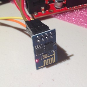
Addendum: The module that I am using is the ESP-01. As you can see, it’s very simple, has only 8 pins, and is not breadboard friendly. Luckily for experimenters, there are other varieties of boards available based upon the same chipset. For instance, the ESP-04 has seven GPIO pins broken out, and can needs an external antenna. The ESP-201 is much more breadboard friendly, and includes both an on-board antenna, and UFL connector for an external antenna. There are lots of other types too, all very reasonably priced. If you haven’t bought the ESP-01 already, some of these other boards might be better to experiment with. But there are also people making various adapters for the ESP-01, such as the ESP8266 buddy, which sells for a paltry $2.50 and can adapt the ESP-01 to your breadboard. I think I’ll be getting a few of these.

First electrons for the ESP8266…

IMG_5702In the telescope making world, we call the first time that a telescope is used to look at the sky “first light”. I’ve decided to call the first time I load some code onto a new development board “first electrons”.

A few weeks ago, when I did a video that illustrated some of the bucket of development boards that I had lying around, I decided that I should at least make a sincere effort to try to do something, anything, with each of them. Since then, I’ve discovered platformio which has enabled me to at least get some code running on the more obscure ARM based boards that I had lying around. Buoyed by that positive experience, I sought to see how I could get code running on some of the other boards. Tonight’s board was the ESP8266, a little cheap board (I paid $6 or so for mine, I’ve seen them on eBay for as little as $3) which are often used as serial-Wifi links, but which actually include a nifty little 32 bit SOC.

Luckily, the gods have smiled in the form of a three part article (Part 1 Part 2 Part 3) by Alasdair Allen for Make magazine. Previously, getting code to compile onto the ESP8266 required finding the right version of gcc and the download esptool, configuring it… Who has the time? What’s awesome is that now you can download a version of the Arduino environment that already has the necessary compiler and tools installed, and use the friendly, comfortable Arduino environment to compile and run code.

So, tonight, that’s what I did!

Conveniently, I had an 3.3V FTDI serial cable that I had purchased back when I was experimenting with 3.3V boards. That’s convenient, because otherwise I’d have to wire up a 3.3V voltage regulator, which isn’t hard, but at least takes one more step. Using the diagram in Part 2 of the article listed above, I setup some jumper wires to connect it all up. I then downloaded the necessary version of the Arduino environment (for my Linux laptop), installed it, loaded the WifiServer example application, modified it with my own network’s SSID and password, and tried compilation. It compiled fine, but when I tried to download the new code to the ESP8266, I got a communication error. I double checked all the connections against the diagram, no dice. Hmmph. There was one small bit of confusion that I always have when hooking up serial devices: the RX (receive) pin of one side needs to be connected to the TX (transmit) on the other, and vice versa. But when you try to document this, it can be confusing: if an end of your cable is labelled RX, does it mean that you should attach it to the RX? Or that the other end of the cable is RX, so you should connect it to TX?

I swapped RX and TX. And voila. The download works just fine.

To reboot and run the code, you need to remove one of the ground connections from the boad and cycle the power. I then fired up the serial monitor, changed the baud rate to 115200, and then watched it boot. It printed out that it was attempting to connect to my network, printed a series of periods, and eventually reported it’s IP address.

Nifty! I need to go dig up some current limiting resistors (maybe 220 ohms or so) so I can test it, but I verified that if I accessed http://192.168.1.116/gpio/0, it turns the gpio pin low, and http://192.168.1.116/gpio sends it high. Voila!

Well, with a few caveats. It seemed a little unreliable, and seemed to hang a couple of times. I’m not sure what the deal is. I’m suspicious about how much power my FTDI cable can actually supply, maybe that’s part of it. Or it could be software related. I’ll have to play with it more to be sure. But it’s pretty nifty. I’m sure I’ll be playing with it more. Good stuff.

Addendum: I dug up an LED and a 330 ohm current limiting resistor, and then recorded this trivial little demonstration.


Tiny Implementation of Conway’s Life…

I had a few minutes, so I thought I’d try making a graphics demo that runs on the tiny little 0.96″ OLED display I mentioned last week. One of the first programs I ever wrote was an implementation of Conway’s Game of Life, having learned about it from Martin Gardner’s Mathematical Games column in Scientific American. I remember that on my old Atari 400, it took a couple of seconds at least per generation, at a resolution of just 40×20 or so. Because of the limited memory (and small size of the display) I decided a 96×64 resolution. There is just enough memory to handle two full sized bit buffers. With a bit more work, I could make it work at the full resolution of the OLED display, but you need to do some of the updates in place, which makes it a bit harder.

[sourcecode lang=”cpp”]
//
// a tiny implementation of Conway’s Life
// written by Mark VandeWettering (brainwagon@gmail.com)
// https://brainwagon.org
//

#include "U8glib.h"

#define XSIZE (128-32)
#define XSIZE_UINT8 (XSIZE/8)
#define YSIZE (64)

uint8_t current[YSIZE][XSIZE_UINT8] ;
uint8_t next[YSIZE][XSIZE_UINT8] ;

#define MODX(x) (((x)+XSIZE)%XSIZE)
#define MODY(y) (((y)+YSIZE)%YSIZE)

#define ISSET(a, x, y) \
(a[MODY(y)][MODX(x)/8] & (0x1<<(MODX(x)&7)))

#define SET(a, x, y) \
a[MODY(y)][MODX(x)/8] |= (0x1<<(MODX(x)&7))

U8GLIB_SSD1306_128X64 u8g(U8G_I2C_OPT_NONE);

void
init()
{
int i, j ;
for (j=0; j<YSIZE; j++)
for (i=0; i<XSIZE_UINT8; i++)
current[j][i] = random(256) ;
}

void
setup()
{
randomSeed(analogRead(0));
init() ;
}

void
draw()
{
u8g.setDefaultBackgroundColor() ;
u8g.drawBox(0, 0, 128, 64) ;
u8g.setDefaultForegroundColor() ;
u8g.drawXBM(16, 0, XSIZE, YSIZE, (const uint8_t *) next) ;
}

void
loop()
{
int i, j ;

memset((void *) next, 0, sizeof(next)) ;
for (j=0; j<YSIZE; j++) {
for (i=0; i<XSIZE; i++) {
int sum = 0 ;
if (ISSET(current, i-1, j-1)) sum ++ ;
if (ISSET(current, i , j-1)) sum ++ ;
if (ISSET(current, i+1, j-1)) sum ++ ;
if (ISSET(current, i-1, j )) sum ++ ;
if (ISSET(current, i+1, j )) sum ++ ;
if (ISSET(current, i-1, j+1)) sum ++ ;
if (ISSET(current, i , j+1)) sum ++ ;
if (ISSET(current, i+1, j+1)) sum ++ ;

if (ISSET(current, i, j)) {
if (sum == 2 || sum == 3)
SET(next, i, j) ;
} else {
if (sum == 3)
SET(next, i, j) ;
}
}
}

memcpy((void *) current, (void *) next, sizeof(current)) ;

u8g.firstPage() ;
do {
draw() ;
} while (u8g.nextPage()) ;
}
[/sourcecode]

It works! It initializes the display to random values, and then runs Life. If the display gets boring, just hit the result button….


Discovered a new tool for embedded development: platformio

I’m pretty old school when it comes to development. To me, writing code is something I like to do with vi (the editor that I learned three decades ago) and compile with Makefiles, especially for code that I do myself. In general, I prefer to do my development on either Linux or Mac OS too, so portable tools are my favorite. Increasingly, people have come to rely on complex development environments, many of which include code wizards that generate lots of the boiler plate needed to create applications, complex syntax coloring, and engines to refactor code. These environments are often significantly different from one another, are closed source, or rely on older versions of open source tools (like plugins for eclipse).

This seemed doubly true for this little Freescale development board that has been sitting unused since I purchased it at the last (or was it the one before that) Maker Faire. It is supposedly part of the “mbed” family of dev boards, which is supposed to make development across a variety of similar boards simple. But the reality is a dizzying array of odd products, including a web based IDE that just annoyed and confounded me. So, the board mostly sat unused. I did mention it in my “bucket o’ dev boards” video a couple weeks ago, and I thought “there must be a better way”.

Rather than toil away on my own, I tossed the question to my twitter followers:


Within minutes, @ukscone responded with this suggestion:


I had never heard of platformio, but I quickly read over the quickstart, and was impressed. Basically it’s a fairly simple utility called (appropriately enough) platformio, written in Python, and portable to Windows, Mac OS X and Linux. Compiled within it is knowledge of a large number of supported boards. You can get a list of supported boards by typing “platformio boards”, and you’ll get the output.

Platform: atmelavr
---------------------------------------------------------------------------
Type                  MCU            Frequency  Flash   RAM    Name
---------------------------------------------------------------------------
flora8                atmega32u4     8Mhz      28Kb    2Kb    Adafruit Flora
trinket3              attiny85       8Mhz      8Kb     512B   Adafruit Trinket 3V/8MHz
trinket5              attiny85       16Mhz     8Kb     512B   Adafruit Trinket 5V/16MHz
btatmega168           atmega168      16Mhz     14Kb    1Kb    Arduino BT ATmega168
btatmega328           atmega328p     16Mhz     28Kb    2Kb    Arduino BT ATmega328
diecimilaatmega168    atmega168      16Mhz     14Kb    1Kb    Arduino Duemilanove or Diecimila ATmega168
diecimilaatmega328    atmega328p     16Mhz     30Kb    2Kb    Arduino Duemilanove or Diecimila ATmega328
esplora               atmega32u4     16Mhz     28Kb    2Kb    Arduino Esplora
ethernet              atmega328p     16Mhz     31Kb    2Kb    Arduino Ethernet
fio                   atmega328p     8Mhz      30Kb    2Kb    Arduino Fio
leonardo              atmega32u4     16Mhz     28Kb    2Kb    Arduino Leonardo
megaADK               atmega2560     16Mhz     248Kb   8Kb    Arduino Mega ADK
megaatmega1280        atmega1280     16Mhz     124Kb   8Kb    Arduino Mega or Mega 2560 ATmega1280
megaatmega2560        atmega2560     16Mhz     248Kb   8Kb    Arduino Mega or Mega 2560 ATmega2560 (Mega 2560)
micro                 atmega32u4     16Mhz     28Kb    2Kb    Arduino Micro
miniatmega168         atmega168      16Mhz     14Kb    1Kb    Arduino Mini ATmega168
miniatmega328         atmega328p     16Mhz     28Kb    2Kb    Arduino Mini ATmega328
atmegangatmega168     atmega168      16Mhz     14Kb    1Kb    Arduino NG or older ATmega168
atmegangatmega8       atmega8        16Mhz     7Kb     1Kb    Arduino NG or older ATmega8
nanoatmega168         atmega168      16Mhz     14Kb    1Kb    Arduino Nano ATmega168
nanoatmega328         atmega328p     16Mhz     30Kb    2Kb    Arduino Nano ATmega328
pro8MHzatmega168      atmega168      8Mhz      14Kb    1Kb    Arduino Pro or Pro Mini ATmega168 (3.3V, 8 MHz)
pro16MHzatmega168     atmega168      16Mhz     14Kb    1Kb    Arduino Pro or Pro Mini ATmega168 (5V, 16 MHz)
pro8MHzatmega328      atmega328p     8Mhz      30Kb    2Kb    Arduino Pro or Pro Mini ATmega328 (3.3V, 8 MHz)
pro16MHzatmega328     atmega328p     16Mhz     30Kb    2Kb    Arduino Pro or Pro Mini ATmega328 (5V, 16 MHz)
robotControl          atmega32u4     16Mhz     28Kb    2Kb    Arduino Robot Control
robotMotor            atmega32u4     16Mhz     28Kb    2Kb    Arduino Robot Motor
uno                   atmega328p     16Mhz     31Kb    2Kb    Arduino Uno
yun                   atmega32u4     16Mhz     28Kb    2Kb    Arduino Yun
digispark-tiny        attiny85       16Mhz     5Kb     512B   Digispark (Default - 16 MHz)
digispark-pro32       attiny167      16Mhz     14Kb    512B   Digispark Pro (16 MHz) (32 byte buffer)
digispark-pro64       attiny167      16Mhz     14Kb    512B   Digispark Pro (16 MHz) (64 byte buffer)
digispark-pro         attiny167      16Mhz     14Kb    512B   Digispark Pro (Default 16 MHz)
engduinov1            atmega32u4     8Mhz      28Kb    2Kb    Engduino 1
engduinov2            atmega32u4     8Mhz      28Kb    2Kb    Engduino 2
engduinov3            atmega32u4     8Mhz      28Kb    2Kb    Engduino 3
lilypadatmega168      atmega168      8Mhz      14Kb    1Kb    LilyPad Arduino ATmega168
lilypadatmega328      atmega328p     8Mhz      30Kb    2Kb    LilyPad Arduino ATmega328
LilyPadUSB            atmega32u4     8Mhz      28Kb    2Kb    LilyPad Arduino USB
168pa16m              atmega168p     16Mhz     15Kb    1Kb    Microduino Core (Atmega168PA@16M,5V)
168pa8m               atmega168p     8Mhz      15Kb    1Kb    Microduino Core (Atmega168PA@8M,3.3V)
328p16m               atmega328p     16Mhz     31Kb    2Kb    Microduino Core (Atmega328P@16M,5V)
328p8m                atmega328p     8Mhz      31Kb    2Kb    Microduino Core (Atmega328P@8M,3.3V)
32u416m               atmega32u4     16Mhz     28Kb    2Kb    Microduino Core USB (ATmega32U4@16M,5V)
1284p16m              atmega1284p    16Mhz     127Kb   16Kb   Microduino Core+ (ATmega1284P@16M,5V)
1284p8m               atmega1284p    8Mhz      127Kb   16Kb   Microduino Core+ (ATmega1284P@8M,3.3V)
644pa16m              atmega644p     16Mhz     63Kb    4Kb    Microduino Core+ (Atmega644PA@16M,5V)
644pa8m               atmega644p     8Mhz      63Kb    4Kb    Microduino Core+ (Atmega644PA@8M,3.3V)
panStampAVR           atmega328p     8Mhz      31Kb    2Kb    PanStamp AVR
protrinket3ftdi       atmega328p     16Mhz     28Kb    2Kb    Pro Trinket 3V/12MHz (FTDI)
protrinket3           atmega328p     12Mhz     28Kb    2Kb    Pro Trinket 3V/12MHz (USB)
protrinket5ftdi       atmega328p     16Mhz     28Kb    2Kb    Pro Trinket 5V/16MHz (USB)
protrinket5           atmega328p     16Mhz     28Kb    2Kb    Pro Trinket 5V/16MHz (USB)
raspduino             atmega328p     16Mhz     30Kb    2Kb    Raspduino

Platform: atmelsam
---------------------------------------------------------------------------
Type                  MCU            Frequency  Flash   RAM    Name
---------------------------------------------------------------------------
due                   at91sam3x8e    84Mhz     512Kb   32Kb   Arduino Due (Programming Port)
dueUSB                at91sam3x8e    84Mhz     512Kb   32Kb   Arduino Due (USB Native Port)
digix                 at91sam3x8e    84Mhz     512Kb   28Kb   Digistump DigiX
sainSmartDue          at91sam3x8e    84Mhz     512Kb   32Kb   SainSmart Due (Programming Port)
sainSmartDueUSB       at91sam3x8e    84Mhz     512Kb   32Kb   SainSmart Due (USB Native Port)

Platform: freescalekinetis
---------------------------------------------------------------------------
Type                  MCU            Frequency  Flash   RAM    Name
---------------------------------------------------------------------------
IBMEthernetKit        mk64fn1m0vll12 120Mhz    1024Kb  256Kb  Ethernet IoT Starter Kit
frdm_k20d50m          mk20dx128vlh5  48Mhz     128Kb   16Kb   Freescale Kinetis FRDM-K20D50M
frdm_k22f             mk22fn512vlh12 120Mhz    512Kb   128Kb  Freescale Kinetis FRDM-K22F
frdm_k64f             mk64fn1m0vll12 120Mhz    1024Kb  256Kb  Freescale Kinetis FRDM-K64F
frdm_kl05z            mkl05z32vfm4   48Mhz     32Kb    4Kb    Freescale Kinetis FRDM-KL05Z
frdm_kl25z            mkl25z128vlk4  48Mhz     128Kb   16Kb   Freescale Kinetis FRDM-KL25Z
frdm_kl46z            mkl46z256vll4  48Mhz     256Kb   32Kb   Freescale Kinetis FRDM-KL46Z

Platform: nordicnrf51
---------------------------------------------------------------------------
Type                  MCU            Frequency  Flash   RAM    Name
---------------------------------------------------------------------------
wallBotBLE            nrf51822       16Mhz     128Kb   16Kb   JKSoft Wallbot BLE
nrf51_dk              nrf51822       32Mhz     256Kb   32Kb   Nordic nRF51-DK
nrf51_dongle          nrf51822       32Mhz     256Kb   32Kb   Nordic nRF51-Dongle
nrf51_mkit            nrf51822       16Mhz     128Kb   16Kb   Nordic nRF51822-mKIT
redBearLabBLENano     nrf51822       16Mhz     256Kb   16Kb   RedBearLab BLE Nano
redBearLab            nrf51822       16Mhz     256Kb   16Kb   RedBearLab nRF51822
seeedTinyBLE          nrf51822       16Mhz     256Kb   16Kb   Seeed Tiny BLE
hrm1017               nrf51822       16Mhz     256Kb   16Kb   Switch Science mbed HRM1017

Platform: nxplpc
---------------------------------------------------------------------------
Type                  MCU            Frequency  Flash   RAM    Name
---------------------------------------------------------------------------
blueboard_lpc11u24    lpc11u24       48Mhz     32Kb    8Kb    BlueBoard-LPC11U24
dipcortexm0           lpc11u24       50Mhz     32Kb    8Kb    DipCortex M0
lpc11u35              lpc11u35       48Mhz     64Kb    10Kb   EA LPC11U35 QuickStart Board
lpc4088_dm            lpc4088        120Mhz    512Kb   96Kb   EA LPC4088 Display Module
lpc4088               lpc4088        120Mhz    512Kb   96Kb   EA LPC4088 QuickStart Board
lpc1549               lpc1549        72Mhz     256Kb   36Kb   LPCXpresso1549
mbuino                lpc11u24       48Mhz     32Kb    8Kb    Outrageous Circuits mBuino
seeeduinoArchPro      lpc1768        96Mhz     512Kb   32Kb   Seeeduino-Arch-Pro
lpc11u35_501          lpc11u35       48Mhz     64Kb    10Kb   TG-LPC11U35-501
lpc1114fn28           lpc1114fn28    48Mhz     32Kb    4Kb    mbed LPC1114FN28
lpc11u24              lpc11u24       48Mhz     32Kb    8Kb    mbed LPC11U24
lpc1768               lpc1768        96Mhz     512Kb   32Kb   mbed LPC1768
ubloxc027             lpc1768        96Mhz     512Kb   32Kb   u-blox C027

Platform: ststm32
---------------------------------------------------------------------------
Type                  MCU            Frequency  Flash   RAM    Name
---------------------------------------------------------------------------
disco_f334c8          stm32f334c8t6  72Mhz     64Kb    16Kb   32F3348DISCOVERY
disco_f401vc          stm32f401vct6  84Mhz     256Kb   64Kb   32F401CDISCOVERY
disco_f429zi          stm32f429zit6  180Mhz    2048Kb  256Kb  32F429IDISCOVERY
nucleo_f030r8         stm32f030r8t6  48Mhz     64Kb    8Kb    ST Nucleo F030R8
nucleo_f070rb         stm32f070rbt6  48Mhz     128Kb   16Kb   ST Nucleo F070RB
nucleo_f072rb         stm32f072rbt6  48Mhz     128Kb   16Kb   ST Nucleo F072RB
nucleo_f091rc         stm32f091rct6  48Mhz     256Kb   32Kb   ST Nucleo F091RC
nucleo_f103rb         stm32f103rbt6  72Mhz     128Kb   20Kb   ST Nucleo F103RB
nucleo_f302r8         stm32f302r8t6  72Mhz     64Kb    16Kb   ST Nucleo F302R8
nucleo_f303re         stm32f303ret6  72Mhz     512Kb   64Kb   ST Nucleo F303RE
nucleo_f334r8         stm32f334r8t6  72Mhz     64Kb    16Kb   ST Nucleo F334R8
nucleo_f401re         stm32f401ret6  84Mhz     512Kb   96Kb   ST Nucleo F401RE
nucleo_f411re         stm32f411ret6  100Mhz    512Kb   128Kb  ST Nucleo F411RE
nucleo_l053r8         stm32l053r8t6  48Mhz     64Kb    8Kb    ST Nucleo L053R8
nucleo_l152re         stm32l152ret6  32Mhz     512Kb   80Kb   ST Nucleo L152RE
disco_f051r8          stm32f051r8t6  48Mhz     64Kb    8Kb    STM32F0DISCOVERY
disco_f303vc          stm32f303vct6  72Mhz     256Kb   48Kb   STM32F3DISCOVERY
disco_f407vg          stm32f407vgt6  168Mhz    1024Kb  128Kb  STM32F4DISCOVERY
disco_l152rb          stm32l152rbt6  32Mhz     128Kb   16Kb   STM32LDISCOVERY
disco_f100rb          stm32f100rbt6  24Mhz     128Kb   8Kb    STM32VLDISCOVERY

Platform: teensy
---------------------------------------------------------------------------
Type                  MCU            Frequency  Flash   RAM    Name
---------------------------------------------------------------------------
teensy20              atmega32u4     16Mhz     31Kb    2Kb    Teensy 2.0
teensy30              mk20dx128      48Mhz     128Kb   16Kb   Teensy 3.0
teensy31              mk20dx256      72Mhz     256Kb   64Kb   Teensy 3.1
teensy20pp            at90usb1286    16Mhz     127Kb   8Kb    Teensy++ 2.0

Platform: timsp430
---------------------------------------------------------------------------
Type                  MCU            Frequency  Flash   RAM    Name
---------------------------------------------------------------------------
lpmsp430fr5739        msp430fr5739   16Mhz     15Kb    1Kb    FraunchPad w/ msp430fr5739
lpmsp430f5529         msp430f5529    16Mhz     128Kb   1Kb    LaunchPad w/ msp430f5529 (16MHz)
lpmsp430f5529_25      msp430f5529    25Mhz     128Kb   1Kb    LaunchPad w/ msp430f5529 (25MHz)
lpmsp430fr5969        msp430fr5969   8Mhz      64Kb    1Kb    LaunchPad w/ msp430fr5969
lpmsp430g2231         msp430g2231    1Mhz      2Kb     128B   LaunchPad w/ msp430g2231 (1 MHz)
lpmsp430g2452         msp430g2452    16Mhz     8Kb     256B   LaunchPad w/ msp430g2452 (16MHz)
lpmsp430g2553         msp430g2553    16Mhz     16Kb    512B   LaunchPad w/ msp430g2553 (16MHz)
panStampNRG           cc430f5137     12Mhz     31Kb    4Kb    PanStamp NRG 1.1

Platform: titiva
---------------------------------------------------------------------------
Type                  MCU            Frequency  Flash   RAM    Name
---------------------------------------------------------------------------
lplm4f120h5qr         lplm4f120h5qr  80Mhz     256Kb   32Kb   LaunchPad (Stellaris) w/ lm4f120 (80MHz)
lptm4c1230c3pm        lptm4c1230c3pm 80Mhz     256Kb   32Kb   LaunchPad (Tiva C) w/ tm4c123 (80MHz)
lptm4c1294ncpdt       lptm4c1294ncpdt 120Mhz    1024Kb  256Kb  LaunchPad (Tiva C) w/ tm4c129 (120MHz)

That’s a LOT of different boards, including a large number of the ones I have. I was particularly interested in creating applications for the Freedom K64F board, which is supported. I typed “platformio install freescalekinetis”, and the script went out and found what version of tools it needed (gcc) and what support framework/libraries it needed, and installed them automatically (on Mac OSX/Linux, they end up hidden in the .platformio library in your home directory). You don’t need to go hunting around and find the right version, platformio takes care all of that (and can handle upgrades as new versions are created). In this way, platformio acts rather like a package manager such as apt-get on Linux.

To use platformio to build a new project, you create a directory, cd into it, and then run “platformio init –board=frdm_k64f”. This creates a src and lib directory, and a file called platformio.ini which describes which boards the project can support. It’s possible to create a single project which supports multiple boards (say, many different types of arduino) and build them all simultaneously, but in my case, I just used the one board. I then created this simple little program inside the src directory:

#include "mbed.h"

Serial pc(USBTX, USBRX);

Ticker timer;
DigitalOut led1(LED1);
DigitalOut led2(LED2);
DigitalOut led3(LED3);

int flip = 0 ;

int r=0, g=1, b=1 ;

void
attime()
{
    int t = led1 ;
    led1 = led2 ;
    led2 = led3 ;
    led3 = t ;
}

int
main()
{
        pc.printf("\nHello world.\n") ;
        led1 = r ;
        led2 = g ;
        led3 = b ;

        timer.attach(&attime, 1);
        
        for (;;) {

        }
        
        return 0 ;
}

This is a simple little program that prints “Hello world” back on the USB port, and then blinks the RGB LED in different colors. I didn’t really know much about the library support for these mbed based chips, but I’m old school. Snooping around in the .platformio directory, I found a bunch of header files that hinted at what is possible. I guessed on how this stuff worked, and coded the program up. You can then compile it with “platformio run”, or compile and upload it with “platformio run -t upload”. (There is a way to set it to automatically upload it if it compiles successfully too).

So, within one hour, I had this:


Awesome!

I’m looking forward to doing more experimentation with platformio, and now have it installed on both my Mac and Linux laptops. In addition to some of the odder platforms I have (like the FreeScale or STM32 boards) it also supports the Arduinos. I like the idea of being able to develop code for the Arduino without having to go through their IDE. I did a bit more experimentation with it last night, and got it to generate some display programs for the little OLED display that I wrote about earlier. Platformio also has a library manager which knows about a lot of the popular Arduino libraries, and can automatically download and update those. As I learn more, I’ll try to post more.

Thanks again to @ukscone! Best new thing I’ve discovered in weeks.