Category Archives: Homebrew CPU

More on Caxton Foster’s Blue Architecture…

Okay, it’s been a long time since I wrote anything here. Not really a lot dramatic going on in life, I just have been spending my free time writing for Quora rather than my own blog. But I still am nerding out from time to time. Last night I dusted off an old project of mine and carried it a bit further…

I had written a short post before about a simulator I wrote for Caxton Foster’s “Blue” computer architecture described in his book Computer Architecture. I have the third edition published in 1985. The “Blue” architecture is ridiculously simple: only sixteen instructions, 4096 words of memory, and only one addressing mode. If you click back to my previous post, you’ll see a complete behavioral simulator for it, written in less than an hour.

Somehow this came back up, and I was suddenly intrigued by the idea of trying to write a simple program for it, just to test my ideas about how awful such a machine would be. Ultimately, my goal is to write a simple program that can compute the value of pi to around 100 decimal places. Such a program seems doable, but it’s not a complete cakewalk. But to achieve this, I thought it might be fun to write a simple assembler.

So, I shook the cobwebs that have covered the bits of my brain that understood yacc/lex/bison/flex and wrote a simple assembler for the architecture. It totals only about 250 lines of code, but can handle symbolic labels and all the instructions. It took me about two hours of wall clock time, with my attention split between programming and watching the latest episode of Grimm.

I doubt the assembler is of any real interest, but eventually I’ll get the code onto github.

I then sat down this morning, and wrote this simple program to take the signed value at the memory location VALUE and print it as a signed decimal number. It prints the sign then five digits, with leading zeros if necessary. I didn’t bother to comment
the code, but here it is…

[sourcecode lang=”text”]
PRINTVALUE:
LDA VALUE
JMA NEG
LDA PLUS
OUT
POS:
LDA S0
STA TMP0
SRJ DODIGIT
LDA S1
STA TMP0
SRJ DODIGIT
LDA S2
STA TMP0
SRJ DODIGIT
LDA S3
STA TMP0
SRJ DODIGIT
LDA S4
STA TMP0
SRJ DODIGIT
HLT

DODIGIT:
IOR JMPBIT
STA RETURN
LDA ZERO
STA DIGIT
LOOP: LDA VALUE
ADD TMP0
JMA DONE
STA VALUE
LDA DIGIT
ADD ONE
STA DIGIT
JMP LOOP
DONE:
LDA DIGIT
ADD FE
OUT
RETURN:
JMP 0

NEG:
LDA MINUS
OUT
LDA VALUE
XOR ONES
ADD ONE
STA VALUE
JMP POS

VALUE: .WORD 12323
TMP0: .WORD 0
DIGIT: .WORD 0
S0: .WORD -10000
S1: .WORD -1000
S2: .WORD -100
S3: .WORD -10
S4: .WORD -1
ZERO: .WORD 0
ONE: .WORD 1
ONES: .WORD $FFFF
JMPBIT: .WORD $A000
MINUS: .STRING "-"
PLUS: .STRING "+"
FE: .WORD 48
[/sourcecode]

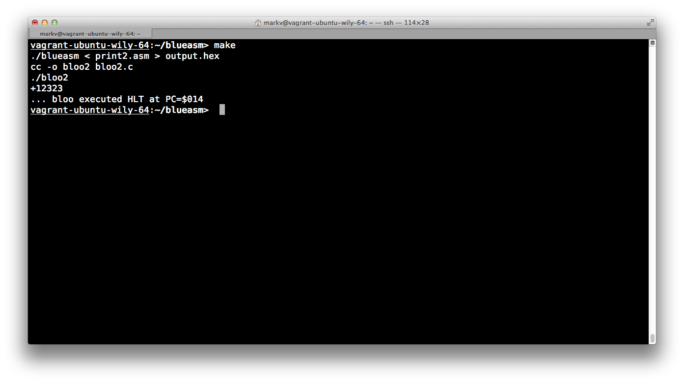
The assembler spits out a series of 16 bit words which can be loaded into my
simulator…

[sourcecode lang=”text”]
0x602B, 0x9024, 0x6038, 0xC000, 0x602E, 0x702C, 0x8014, 0x602F,
0x702C, 0x8014, 0x6030, 0x702C, 0x8014, 0x6031, 0x702C, 0x8014,
0x6032, 0x702C, 0x8014, 0x0000, 0x4036, 0x7023, 0x6033, 0x702D,
0x602B, 0x102C, 0x9020, 0x702B, 0x602D, 0x1034, 0x702D, 0xA018,
0x602D, 0x1039, 0xC000, 0xA000, 0x6037, 0xC000, 0x602B, 0x2035,
0x1034, 0x702B, 0xA004, 0x3023, 0x0000, 0x0000, 0xD8F0, 0xFC18,
0xFF9C, 0xFFF6, 0xFFFF, 0x0000, 0x0001, 0xFFFF, 0xA000, 0x002D,
0x002B, 0x0030,
[/sourcecode]

The data above gets simply compiled into my simulator and runs.

Screen Shot 2016-03-26 at 10.57.16 AM

Okay, so what’s fun to note about this?

There is only a single register, the accumulator. You spend a LOT of time loading things, modifying the value, and storing them back into main memory. There is no “immediate mode”, so you have to create memory locations to store common values like “1” and “0”. DODIGIT is a subroutine, which is called by the SRJ instruction. SRJ puts the PC into the accumulator, and then jumps to the specified address. To “return”, you OR in the bits to the accumulator to form a JMP instruction, and then store that at the end of your subroutine. There is no call stack. Although not demonstrated particularly here, the processor does not implement indexing or indirection. There is also no real condition registers such as CARRY or OVERFLOW, so implementing multi-precision arithmetic might be a challenge.

Foster’s book also details additions to this architecture, eventually becoming INDIGO, an architecture which is rather similar to a PDP-8.

Sure, if you are going to really learn computer archtictures, Patterson and Hennessy is probably a better path, but there is something like of pleasing in this archaic trip down memory lane. My pi computing program will percolate in my brain for a bit, and will find implementation on some other evening.

Addendum: Hackaday recently posted about Al Williams’ FPGA implementation of an architecture which is based upon Foster’s Blue machine. I believe he made a number of changes that make it more practical, but it might be worth looking at. He wrote a monitor, which seems to use opcodes which aren’t compatible with mine.

Addendum2: Pondering it some more throughout the day, it seems difficult to implement my idea of a pi computing program for this virtual machine. All of the algorithms that I can think of require 32 bit numbers, and the Blue architecture simply lacks the capabilities needed to implement it. It also is pretty weak on conditional statements: the only condition that you can branch on is the sign bit of the accumulator.

Ken tinkers with DTL, and SV3ORA’s transistorized 4-bit digital computer made out of discrete DTL

Ken stumbled on one of my earlier posts about DTL (diode transistor logic) and was interested enough to do some basic exploration. He reduced the DTL NAND gate to a double diode, a transistor and two resistors. Ken sent me the LTSpice and EagleCAD screen dumps that fit in about .4″ square:

nand

Pretty cool. In an email, Ken goes a bit further:

I’m working towards a bitslice pcb that implements either an ALU or a Program counter. Remarkably their logic is so similar that a single block of logic could be configured to match either requirement. I think I can get it all on to a 4″ x 2″ pcb with a couple of LEDs and a toggle switch on the front edge. Stack 8, 12 or 16 of these together and you have something similar to the PDP-8.

Awesome Ken! I hope to hear more about this when you have some hardware running.

I haven’t even done any real thinking since then, but I went back and tried to find some more information of people building stuff with DTL logic. I’m not sure if I spotted SV3ORA’s 4 bit digital computer before, but rereading it today, it turned out very cool. He constructed the logic on perfboard with just ordinary components. Very nice.

A transistorized 4-bit digital computer made out of discrete DTL

Addendum: Ken also pointed out the NAND to Tetris course in his email, which I believe I may have blogged about before, but which is a great resource for someone seeking to develop a more complete vertical understanding of computers from the ground up. Ken’s addition of actual soldering to the project makes it even cooler.

Simulation experiments with LT-Spice…

Yesterday, I mentioned Rory’s excellent introduction and exploration into DTL logic. He covers some of the basics here, including circuits for all the basic gates: AND, OR, NOT and NAND. The AND and OR gates are interesting, because they consist entirely of diodes and resistors. They do have the drawback that they are “lossy” (the technical term is non-regenerative). They experience a voltage drop across them, so they can’t be cascaded forever, as the voltage drop continues with each gate, and they ultimately lose the ability to compute effectively. The NOT and NAND gates on the other hand use a typical bipolar NPN transistor, and use the amplifying capability of transistors to regenerate the signal.

I was interested in a couple of things about the circuit though, so I fired up LTSpice for a little computational experiment.

I have played around with simple inverters like this one, which Rory mentioned which I always thought of as an effective inverter. But Rory mentioned that it was unable to run at higher speed (say, around 1Mhz). I was also interested in how the choice of diode affected the circuit.

So, I built it. Rory used BAT42 Schottky diodes, which weren’t in my component catalog, so instead I substituted a 1N5818 diode.

dtl-nand

And sure enough, it works pretty darn well. I coded up a 500kHz clock, and the output looks pretty clean. I fed it two pulse trains one delayed with the other, and it looks pretty good.

trace

If you substitute some of the cheap diodes I have on my bench (like a 1N914 or a 1N4148) you can see that it works pretty well at frequencies around 1000Hz, but fails miserably at frequencies of 1Mhz. Ditto for the simplified inverter circuit we looked at above: it simply can’t function at 500khz. Superimposed with the NAND pulse train, here is the output of the simplified inverter wired to InputA. As you can see, the input pulses just turn into a feeble triangle wave.

inverter

I suspect that thinking about why this is will lead me to a much more robust understanding of transistors.

Tiny-Tim: A DTL computer (in progress)

Previously, I had linked to Rory Mangles’ experiments with relay based computers. He had an incredible build of a relay logic computer called Tiny-8 which used paper as program mamory, inked with a pattern which could be read by photo sensors to sequence the control logic in his computer. I thought it was amazing. But surfing back to his website, he appears to now by working Tiny Tim, a diode-transistor logic (DTL) computer, made from discrete 2N3904 transistors and Schottky diodes. Sadly, there isn’t much actual build here yet (this update is six months old) but there is some good information, and I hope that he’ll pick up the project again.

Here is a link to his video of a simple flip flop:


Designing a full adder with logisim

An anonymous commenter suggested that I look at logisim, a circuit simulator written in Java. It has many nice features. For instance, you can specify a combinatorial circuit either as a truth table or as equations, and it will convert to the other representation (in minimized forms) and will also build a circuit to implement those equations. You can tell it to use only 2 input gates, or even to use only NAND gates, and it will layout a little circuit to implement it.

For instance, I entered the truth table for a full adder, and told it just to use 2 input NAND gates. The resulting (29 gates? I didn’t count carefully) 1 bit full adder emerged as a circuit:

Pretty neat. I am not sure that logisim is quite good enough to design an actual, physical CPU (it doesn’t model propagation delays, as far as I can tell) but it’s a very good tool to exercise your nascent digital design skills. Check it out.

DIY Computer Project

Continuing my obsession with reading up on homebrew CPU projects, I found this incredible blog. Instead of just presenting the completed design, Dawid has presented intermediate posts about his project in progress, detailing some of the choices and techniques he had to make along the way. As is true of most projects like this, it’s hard to know how to get started and gain enough traction to make progress, and details like this can be really helpful and really inspiring.

DIY Computer Project

Addendum: For instance, I’ve been considering writing a gate level simulator (writing code is something I feel comfortable doing) rather than spending huge amounts of time learning Verilog or VHDL. It is somewhat reassuring that Dawid apparently did the same thing. Very interesting.

A basic simulator for Caxton Foster’s “Blue” Architecture…

Yep, been spending some time thinking about homebrew computer architectures. I’ve also been reading Gordon Bell’s Computer Engineering, pondering some of the older and earlier computing architectures. Caxton Foster’s Computer Architecture describes a simple computer architecture called “Blue”, which has only 16 instructions, and uses only direct addressing. It’s a pretty primitive machine (more like a PDP-8’s out of work cousin), but in 30 pages, Foster describes pretty much the complete circuitry needed to implement the machine. I thought I’d write a simple behavoral simulator just to play with, and to see how much of a pain it is to program (answer: pretty big). For now, here’s the code. More later.

[sourcecode lang=”C”]#include <stdio.h>
#include <stdlib.h>

/* _ _
* | |__| |___ ___
* | ‘_ \ / _ \/ _ \
* |_.__/_\___/\___/
*
* An implementation of the simplest version of Caxton Foster’s "Blue"
* machine as described in his book _Computer Architecture_, Third
* Edition, Copyright 1985. Just meant to stimulate some experimentation.
*
* The architecture described is _very_ simple, consisting of just sixteen
* instructions, a single accumulator, no CPU flags like carry or overflow,
* and only direct addressing. This makes programming pretty annoying,
* virtually requiring self-modifying code to do anything non-trivial.
* But in 30 pages, Foster presents pretty much the entire architecture,
* which made me spend 15 minutes to code up a simple behavioral simulator
* and play around with it.
*/

typedef unsigned short Word ;

#define MEMSIZE 4096

Word M[MEMSIZE] = {
0x600C,
0x100B,
0x9004,
0x0000,
0x700C,
0x6008,
0x100B,
0x7008,
0x600C,
0xC000,
0xA000,
1,
-13,
‘H’,
‘e’,
‘l’,
‘l’,
‘o’,
‘ ‘,
‘W’,
‘o’,
‘r’,
‘l’,
‘d’,
‘!’,
‘\n’
} ;

Word A ;
Word Z ;
Word MAR ;
Word MBR ;
Word PC ;
Word IR ;
Word CS ;

void
fetch()
{
Word t ;

/* fprintf(stderr, "… 0x%04x ", PC) ; */
IR = M[PC] ;
PC ++ ;
PC &= (MEMSIZE-1) ;
}

void
execute()
{
int op = IR >> 12 ;
int addr = IR & 0xfff ;

/* fprintf(stderr, "%0x %03x\n", op, addr) ; */

switch (op) {
case 0: /* HLT */
fprintf(stderr, "\n… bloo executed HLT.\n") ;
exit(0) ;
case 1: /* ADD */
A += M[addr] ;
break ;
case 2: /* XOR */
A ^= M[addr] ;
break ;
case 3: /* AND */
A &= M[addr] ;
break ;
case 4: /* OR */
A |= M[addr] ;
break ;
case 5: /* NOT */
A ^= 0xFFFF ;
break ;
case 6: /* LDA */
A = M[addr] ;
break ;
case 7: /* STA */
M[addr] = A ;
break ;
case 8: /* SRJ */
A = PC & 0xFFF ;
PC = addr ;
break ;
case 9: /* JMA */
if (A&0x8000)
PC = addr ;
break ;
case 0xA: /* JMP */
PC = addr ;
break ;
case 0xB: /* INP */
A = getchar() ;
break ;
case 0xC: /* OUT */
putchar(A) ;
fflush(stdout) ;
break ;
case 0xD: /* RAL */
if (A & 0x8000)
A = (A << 1) | 1 ;
else
A = (A << 1) ;
break ;
case 0xE: /* CSA */
A = CS ;
break ;
case 0xF: /* NOP */
break ;
}
}

int
main(int argc, char *argv[])
{
for (;;) {
fetch() ;
execute() ;
}
return 0 ;
}

[/sourcecode]

John Doran’s D16 Homebrew Computer

Just another link to inspire me in my glacial moves toward designing a CPU of my own:

The D16/M is a general-purpose, stored-program, single-address, 16-bit digital computer using two’s complement arithmetic. It manages subroutine calls and interrupts using a memory stack. The processor may directly address 64K words of memory or I/O. Its timing and control unit is microprogrammed (fully horizontal, with a 72-bit control word).

John Doran’s D16

Treasure Trove of Ideas Re: Homebrew CPUS

Dieter Muller has an amazingly interesting collection of interesting ideas about building homebrew cpus with TTL logic. I’m sure to old school logic designers, most of these are old hat, but to the nearly crazed home experimenter, they are quite illuminating. His hints on ALU design are what brought me to the site, so I’m leaving this breadcrumb on my blog so I can find it again easily.

Dieter’s Homepage..

The Duo Adept, another 8 bit computer built from TTL logic…

In a previous blog post about a year ago, I pointed you at Jack Eisenmann’s 4 bit computer built from TTL chips. It was cool, made entirely on breadboards tucked away inside a big plastic container. Or, I used to think it was cool, until I saw what he’s been up to: an 8 bit computer, complete with video interface. All done on an ungodly number of breadboards. It takes a certain kind of obsessive lunacy to make one of these, and I can appreciate it.


His web page detailing the Duo Adept..