Category Archives: LED

The ESP8266…

I’ve been quiet lately, but mostly because what tinkering I’ve been doing has been relatively limited in scope. But one thing I have begun to play with a lot are various tiny development boards based upon the Espressif ESP8266 WiFi chip. I’ve mentioned them a bit before, but I’ve made some progress since then (and the platform has as well) so I thought I would give you an update.

51oc+lvXC3L._SX300_
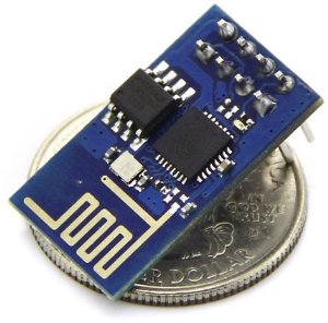
First of all, the hardware. There are lots of different development boards which use this chipset. The smallest and least expensive is the ESP-01, which probably costs around $3.50 if you look around, maybe even cheaper via eBay. You’ll pay about $7 or so from Amazon or the other major dealers, but companies like ElectroDragon have them for half that. The ESP-01 is really small, but not very breadboard friendly, since it has its 8 pins in a 2×4 array. They also have a fairly limited number of GPIO pins: notably, two (and GPIO 0 needs to be able to be pulled low to start the flash bootloader).

You can get a plethora of other modules (popular ones are the ESP-12 surface mount modules) that bring more pins to the output, but I wanted something with the ability to be put in a breadboard for experimentation, so I stared at three different modules:

  • The NodeMCU which I purchased from Electrodragon. This was the first version of this board, which has a couple of quirks: it’s wide, almost takes up the entire width of the breadboards that I have, which is kind of annoying. It also has a yellow soldermask with white lettering, which is pretty difficult to read, even with bright light and magnification. And, it uses an offbrand serial/USB chip which is supported under Linux, but might require driver downloads if you have Windows or Mac OS X. I’m told that their new version fixes that: it’s narrower because it is based upon an ESP-12E module, it uses the slightly more common CP2102 chip for serial/USB and as a bonus, it doesn’t require you to hold down the rest key to reprogram. I don’t have one of those yet, but it seems like a pretty nice little module.
  • The Adafruit Huzzah board is similar to the ElectroDragon, but has a couple of nice changes. First of all, it’s a product of Adafruit, and I like to support companies that actively support user communities. It’s similarly small, but has much nicer labels that are reasonably easy to read. Unlike the ElectroDragon board, it has just a raw TTL serial connection (six pins on the end) so you’ll need a USB/Serial cable to talk to it and program it. Luckily, this design has included circuitry to change the levels of the TX/RX lines to be compatible with 5V programming cables, which are a bit more common. Note: there is no level shifting on the other GPIO pins. The board comes shipped with a couple of rows of header pins you have to snap off and solder in place yourself. I would have liked it had they included a 6 pin right angle set too: when you solder in the programming pins, they are pretty close to the reset button which you need to hit fairly often, making them right angle would have helped. It comes programmed with the NodeMCU firmware, which is based upon the Lua programming language, which is a compact programming language that has gained some popularity in the game world. More on that later…
  • The Sparkfun “Thing” board is a similar board which is a bit more expensive ($16) but has some additions that make it attractive. Most notably, it has an on-board LiPo battery charger and power supply, which means that if you wanted to do something battery powered, this might be a good way to go. Like the Huzzah board, it needs an FTDI cable, but it does NOT have levelshifting, you should use the 3.3V programming cables. I don’t have one of these yet, but I probably will soon. It should also be noted that Sparkfun also has a $15 WiFi Shield that you can attach to the Arduino, which is basically has the same brains, but put in a formfactor that can easily attach to an Arduino. Very nice.

Out of the box, each of these boards except the Adafruit Huzzah supports the “AT command” firmware. If you are as old as me and remember the days of the Hayes Modem, you might remember issuing AT commands to the modem to get it to dial a remote BBS. This firmware works kind of the same way: there are a bunch of commands which begin with AT that allow you to connect to local WiFi networks, establish network connections, and send and receive data. If you have a project which uses the Arduino (or almost any other small micro like the Teensy) that you want to connect to the Internet via WiFi, using one of these modules with the AT command firmware might be a reasonable way to go. You merely attach the serial port on the ESP8266 board to your Arduino, and then you can send commands to it and receive data back. Very cute.

But the system itself is more powerful. The processor on the board is surprisingly capable: it’s a 32 bit processor, running at 80Mhz, with 64 K of instruction RAM, 96K of data RAM, and 64K of boot ROM. It has 9 GPIO pins, and can do I2C, SPI, PWM, and even has a slightly odd ADC channel (max voltage 1.8v). And, what’s pretty neat is that the manufacturer has done quite a bit to encourage people to program them. They release a set of SDK libraries which are reasonably complete, and lots of people have starting writing their own programs in C/C++. When used this way, the boards may not even need a separate microcontroller like the Arduino: it can do all the work itself.

I’m not going to explain all the details here, but you’ll need a compiler and a tool for downloading code to the ESP8266. There are several ways that you can do that:

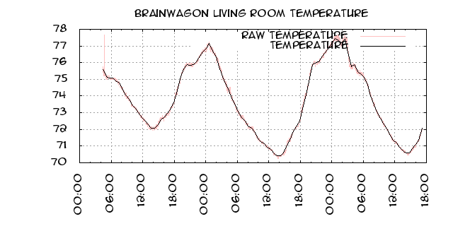
  • I like to use PlatformIO, which supports ESP8266. If you are interested in doing code for embedded development boards, check out platformio. I’ve mentioned it before, and I’m super glad that the ESP8266 is supported. Basically, it’s a simple command line shell that enables you to ignore a lot of the download/compile/configuration of the tools you’ll need. You simply tell it to build a project for the ESP-01 with the command “platformio init –board=esp-01” and it makes sure that you have all the right libraries/compilers/utilities. It also installs the Arduino framework for Espressif, which means that if you are used to writing Arduino code with the setup/loop structure, you can write code the same way for the ESP8266. Earlier last week, I used this to code up a simple sketch which took temperature readings from a DS18B20 1-Wire temperature module, and upload it to the phant.io data server on data.sparkfun.com. It’s been running for a few days, and if I pull down the information, you can see how the temperature in my living room has been varying…temp
  • You can use ESP8266 support in the Arduino environment. Modern versions of the Arduino software support installation of third party packages that allow you to use the Arduino IDE with third party platform packages. I haven’t tried this, but this is probably the easiest way to get into programming the bare metal.
  • You can use pfalcon’s Open SDK. I think this is a tiny bit misleading: it’s really just an easy way to build the necessary cross compilers: the SDK is still the no-source binary blobs that Espressif sends you. I also had some difficulty getting this to work properly on Mac OS X. But if you want to recompile the “nodemcu” firmware from source, you’ll need this.

There are a couple of issues which seem to be different between the various boards as well. Most of them require that you pull the GPIO 0 pin low (tie it to ground) to reflash the chip. On the ESP-01 boards, you usually do this by moving a jumper to tie it low, then powering up the chip. On the NodeMCU boards, they have a nifty little button, if you hold it down before starting programming, it will do the right thing. The Adafruit Huzzah board is a little bit odd, you hold down the GPIO 0 button, and while holding it down, click the RESET button and release it. I understand that the Sparkfun boards might actually use the DTR (or some such) pin on the programming cable to do the switching for you, which means that it can do so without button pressing. Whatever board you get, check documentation online and see what you need to do to make it work.

Another issue is labelling of pins. If there is one thing that Arduino got right, it was that if you use the pin number which are printed on the board to identify each pin, you’ll be fine: the table which converts between those numbers and the proper port/offset is well handled, and things mostly just work. On the ESP-01, there are simply no labels. On the NodeMCU, many of the pins are labelled D0-D7. On the Adafruit, pins are labelled with the underlying GPIO port numbers. But if you use those numbers in a sketch, imagining that something labeled pin 16 should enable you to call it pin 16, you’d be mistaken. And, it’s far from clear to me that boards do this at all consistently: you might need to think really hard to find out what the mapping is, and it might vary (I’m pretty sure that the NodeMCU hardware and the Adafruit Huzzah have different mappings, so the code will have to be different to address the same pin.)

All that being said, the ESP8266 in its many forms is a very cool little processor, all priced at a pittance. Worth exploring. I’ll have more information on projects as I move forward on them.

Tinkering with individually addressable LEDs…

Blinking LEDS...While digging around looking for an LCD module I thought I had stashed somewhere, I encountered a bag with some of 8mm individually addressable RGB LEDs that I had never done anything with. For fun, I thought I’d wire a few of them up on my breadboard and see if I could get them to do something.

These things are cool. Most RGB LEDs have four leads, with one common annode (or cathode) and three other pins, each of which connects to the different color LED. To dim them and generate arbitrary colors, you need to have three pins which are attached to a pulse width modulated pin. To address a bunch of them individually would require a bunch of pins.

But these LEDs are different. It’s true, they have only four pins. But they are constructed to act independently. The four pins are a 5v power pin, a ground, and a data-in and data-out. You can chain arbitrary numbers of them together by hooking the data-out from one LED into the data-in of the next.

To demonstrate this, I thought I’d hook hook three of them together, and see what I could do. It wasn’t obvious to me from the datasheet that I found how the pins were label. Luckily, AdaFruit had a nice diagram that showed how the pins were ordered. I positioned the flat side of each led to the right, hooked all the +5V and ground connections up, and then wired the data-out of each stage to the data-in of the next stage. I then looked up the Arduino, which is dead simple: one output pin to the first LED data-in, and hook up the common ground.

led

To drive this requires a bit of code. The library that everyone seems to use is the Adafruit NeoPixel library. Oh, did I mention? The same LEDs are found in preformed strips like this one. If you need a lot of LEDs in a strip, this is a good way to go. But for just a few LEDs, these through hole parts can be fun.

I downloaded the Adafruit library, and wrote up this chunk of code.

[sourcecode lang=”cpp”]
#include <Adafruit_NeoPixel.h>

const int led_pin = 6 ;

Adafruit_NeoPixel strip(3, led_pin, NEO_RGB + NEO_KHZ800);

void
setup()
{
strip.begin();
}

int cnt = 0 ;

int col[3][3] = {
{255, 0, 0},
{0, 255, 0},
{0, 0, 255}
} ;

void
loop()
{
int i, idx ;
for (i=0; i<3; i++) {
idx = (cnt + i) % 3 ;
strip.setPixelColor(i, strip.Color(col[idx][0], col[idx][1], col[idx][2]));
}
strip.show() ;
cnt++ ;
cnt %= 3 ;
delay(500) ;
}
[/sourcecode]

Nothing too exciting, but it’s been a fun little thing to tinker with. It’s nifty to drive a large number of LEDs using only a single digital pin from a microcontroller. I’ll have to come up with a project to use them sometime.

More ESP8266 Experimentation: Giving it the Boot…

Got a chance to play around a bit more with the ESP8266 tonight. I dug out a nice little dual output power supply board that I had got from tautic.com with the hope that it would eliminate some of the erratic behavior that I had observed before. Sadly, that didn’t seem to solve my problem. Luckily, after a bit of googling, I think I see what’s going on.

First of all, the ESP-01 module I have is really limited in its number of pins. There are only a total of 8 pins brought on onto the header. They are:

ESP8266_pinout

  • UXTD — connects to the UART 0 transmit pin
  • CH_PD — must be tied high (to 3.3v) to boot
  • RST — pull low to reset
  • VCC — connect to 3.3V power supply
  • GND
  • GPIO2 — general purpose IO pin (but see below)
  • GPIO0 — general purpose IO pin (but see below)
  • URXD — connects to UART 0 receive pin

I had read that in order to flash, you needed to set GPIO0 low (tie it to ground) but for normal operation, you could either pull it high, or simply let it float. That seemed to work fine. Then, I tried to use GPIO2 to power a small led. It would work fine if I hooked it up after booting, but if I was wired up both the red and blue leds would come on, and it would not boot properly. It turns out that GPIO2 must be left high or floating for normal operation to occur.

This article explains some of the issues. It appears that a 2.2k pull up resistor will probably do the trick. It’s too late tonight for me to scramble around, but I’ll try it tomorrow.

Making a simple RC switch…

Over the last couple of years, I’ve spent a little bit of time making fixed wing aircraft from Dollar Tree foam. The results have been interesting and fun, but I’ve found that the need to find relatively large areas to fly means that it’s harder to go fly than I would like. On the other hand, multicopters require relatively less area, and I suspect I could do some test flights almost anywhere. So, over the last few months I’ve begun to accumulate the necessary parts to put one together. As this project continues, I’ll write up some more.

But one of the things I thought about today in between World Cup matches was putting some LED lights on the quadcopter. Besides just looking cool, they are especially useful on quadcopters because they allow you to see the orientation of the quadcopter more easily.

My RC mentor Mark Harrison has some notes about he wired up LEDs on his quadcopter. The basic idea is to get some LED strips, and then power them from a brushed ESC (like this one for $4.95) driven by a spare channel on the RC receiver. It’s a pretty good way to go.

But I wondered if I could do better. I’ve made a Christmas hat with LEDs before, driven by an Atmel ATTiny13, surely I could homebrew something…

So here’s where my thought is: I want to create a small pc board with just a few components. It will be powered from the receiver, and will read the servo control channel, and will use an Atmel ATTiny85 (I have a dozen on hand that I got from Tayda Electronics for about about $1.12 each, and they have 8K of memory, plenty for this application). At it’s simplest, we want the program to configure one pin as an input, and one pin as an output. The servo control signal looks like this:

ServoPwm

The pulse will be somewhere between 1ms and 2ms long. The ATTiny just needs to monitor the channel, and if the pulse is longer than 1.5ms, it will set the output high, otherwise set the output low. And that is pretty easy.

In the past, I’ve used avr-gcc to program these tiny chips. For the ATTiny13 with just 1k of flash, that’s pretty understandable. But it turns out that with a bit of work, you can use the Arduino environment to program the ATTiny85s. This website gives most of the details. It’s pretty easy, and I got my MacBook all configured in just a few minutes. Then, I entered and compiled this (as yet untested) code:

[sourcecode lang=”cpp”]
/*
* I thought I would dummy up a simple RC controlled switch using
* an Atmel ATTINY85 processor, but code it all in the Arduino
* environment. The idea is to use pulseIn() to read the data signal
* from the RC receiver, and threshold it, setting an output pin
* if the pulse length is > 1500 ms, and clearing it if less.
* Very simple. It should be able to be powered directly from the
* receiver, and if we had some kind of FET we can switch large loads
* (like a strip of LEDS).
*/

int inputPin = 0 ;
int outputPin = 1 ;

void
setup()
{
pinMode(inputPin, INPUT) ;
pinMode(outputPin, OUTPUT) ;

// if we never get a pulse, we want to make sure the
// ourput stays switched off.
digitalWrite(outputPin, LOW) ;
}

void
loop()
{
digitalWrite(outputPin,
pulseIn(inputPin, HIGH) > 1500 ? HIGH : LOW) ;
}
[/sourcecode]

Couldn’t be much easier. If you hooked up an led with a current limiting resistor to pin 1, you can test this (I’ll put up some video once I get it going). To power a larger 12v string (like this red LED string I got for $8.90 for 5m from Amazon) you’ll use that output to power a FET to switch the much larger current, but that’s dead simple too. I can probably run the ATTiny off its internal oscillator at just 1Mhz.

But as cheap as that is, it’s probably not worth the cost of home brewing one.

But of course, you don’t need to stop with this stupid application. You have a total of five or six pins, so you can easily control multiple strings. You can also implement more sophisticated controls: instead of just using an on/off signal, you can look for short switch flips versus long switch flips, and change into different blinking modes. A short flip might make the landing lights blink. A long one turns them on steady. You could even use the ATTiny to drive RGB addressable LEDS (check out this Instructable for details). Different flips might turn on different colors, or switch between Larson scanner modes… blinking… the skies the limit.

I’ll let you know when I get more of this done.

Project Completed: My $.99 Christmas LED hat, with ATtiny13 controller

Well, it’s done! Here’s my ATtiny13 controlled Christmas LED hat. It consists of an 8 pin, ATtiny13 microcontroller, a pair of 2N3904 transistors and some 1K resistors, a 7805 voltage regulator with two filter caps, and a switch, all mounted on a Radio Shack perfboard inside an Altoids tin. I’m rather pleased with the way it turned out. I always like it when a project goes from the breadboard to a final mounting in a box.


Addendum: Here’s the schematic for the entire circuit. Nothing too surprising, but you should be able to follow it if you need to.

Carmen makes an Arduino Stoplight

Today, Carmen decided that she wanted to give Arduino programming a try. She’s an experienced programmer, but had never tried any of this small embedded stuff, and knows relatively little about electronics, but with a little direction from me, she got the Arduino development environment installed, and we did a bit of playing around. I showed how we could blink an LED, and then showed her how to read switches and even drive a servo motor. She then walked through some of Lady Ada’s tutorials and ended up scavenging a red, green, and yellow LED from some old throwies we had, and coding up a little stop light application:

Here’s the code:

[sourcecode lang=”cpp”]
// Stoplight
// Introductory Arduino program – Carmen & Mark VandeWettering 12/11/11
// with thanks to : http://www.ladyada.net/learn/arduino/lesson3.html
//
int redPin = 12; // Red LED connected to digital pin 12
int greenPin = 11; // Green LED connected to digital pin 11
int yellowPin = 13; // Yellow LED connected to digital pin 13
int delayTime = 1000; // initiate a delaytime amount here

void setup() // run once, when the sketch starts
{
pinMode(redPin, OUTPUT); // sets the digital pin as output
pinMode(greenPin, OUTPUT); // sets the digital pin as output
pinMode(yellowPin, OUTPUT); // sets the digital pin as output
}

void loop() // run over and over again
{
digitalWrite(redPin, HIGH); // sets the Red LED on
delay(delayTime); // waits the delayTime
digitalWrite(redPin, LOW); // sets the Red LED off
digitalWrite(greenPin, HIGH); // sets the Green LED on
delay(delayTime*5); // waits the delayTime * 5
digitalWrite(yellowPin, HIGH); // sets the Yellow LED on
digitalWrite(greenPin, LOW); // sets the Green LED off
delay(delayTime); // waits the delayTime
digitalWrite(yellowPin, LOW); // sets the Yellow LED off (and continue the loop)
}
[/sourcecode]

If you have any experience with programming at all, the Arduino should be pretty easy. If you don’t, it will take a bit more work, but it’s still doable. Give it a try!